
PCB Assessment Case
3D Wheel Alignment Camera Board Short-Circuit Repair
Board-level assessment plan for a short-circuited 5MP camera module from an SM-V2 3D wheel-alignment system.
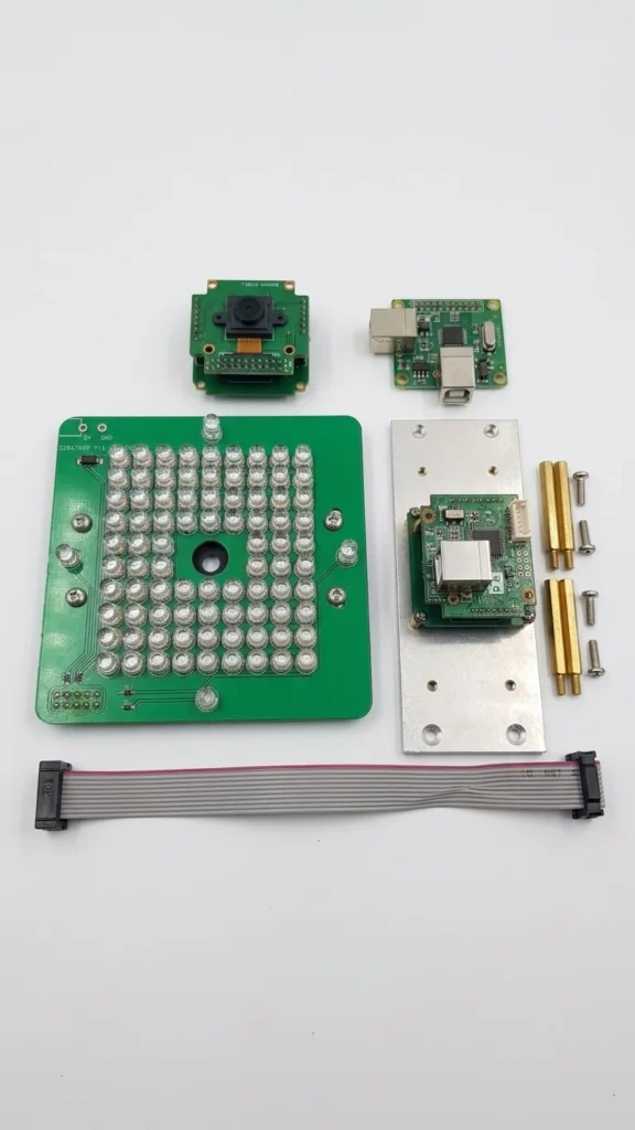
Board typeCamera and sensor board assembly
ApplicationAutomotive Service Equipment
ServiceShort-Circuit Diagnosis
Fault Description
”My SM-V2 3D wheel aligner (with 5MP cameras) had a short circuit, and it blew out one of the camera boards.“
Diagnosis & Repair Process
The customer reported a short-circuit failure affecting one 5MP camera channel in an SM-V2 3D wheel-alignment machine.
This type of module may combine an illumination board, camera-control board, image-sensor board, heat sink, standoffs, and ribbon interconnects. Each layer must be documented before disassembly so orientation and spacing can be restored correctly.
1. Inspection and Diagnostics
Step 1: Disassembly and Visual Inspection
-
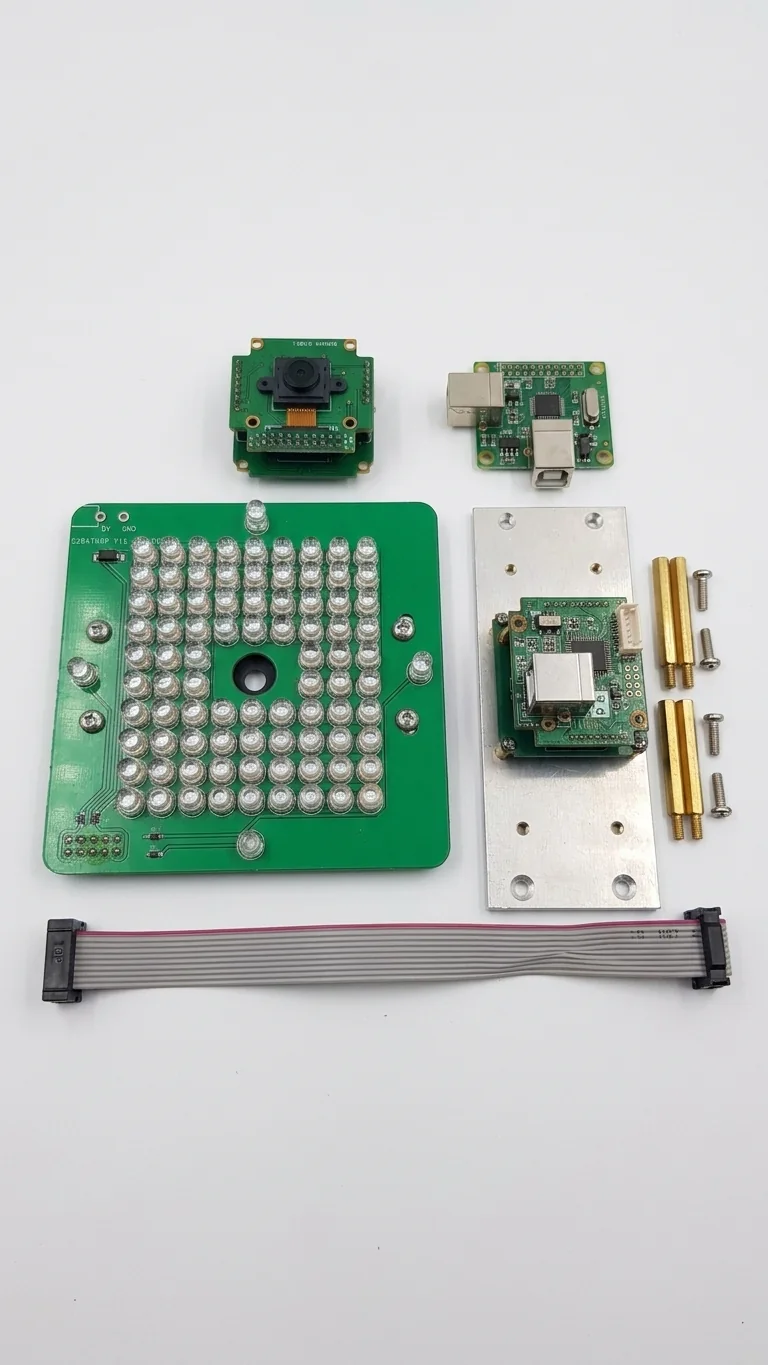
Disassembled the multi-layer stack structure to inspect the LED illumination board and camera control board separately.
-
Removed the boards from the aluminum heat sink and placed them on an anti-static mat for visual inspection.
-
Inspection Image (Figure 1): Displays the fully disassembled assembly, including the main LED PCB, small camera sensor board, aluminum heat sink, brass standoffs, and ribbon cable.
Step 2: Short Circuit Localization
-
Focused troubleshooting on the small camera control board since it manages USB power input and onboard power distribution.
-
Applied controlled power injection using a benchtop power supply (0V–30V / 0A–5A), injecting 1V into the main 5V power rail while monitoring current draw.
-
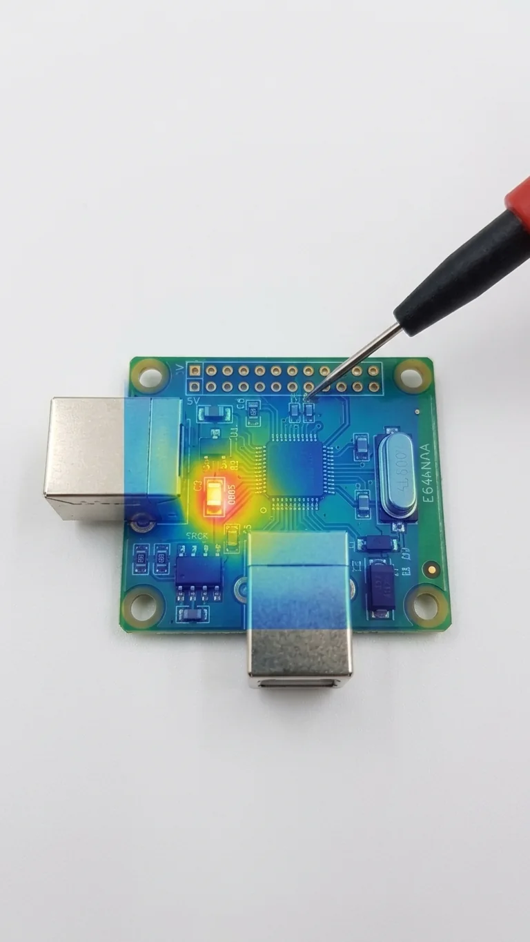
Scanned the board using a high-resolution thermal imaging camera.
Inspection Image (Figure 2): Shows a close-up of the camera PCB with a thermal overlay revealing a distinct hotspot. A 0805 SMD capacitor (10μF) glows bright orange, confirming heavy heat generation from a direct short. Surrounding components remained cool (blue/green). Multimeter testing confirmed near 0 Ω resistance across the capacitor.
2. Repair Measures
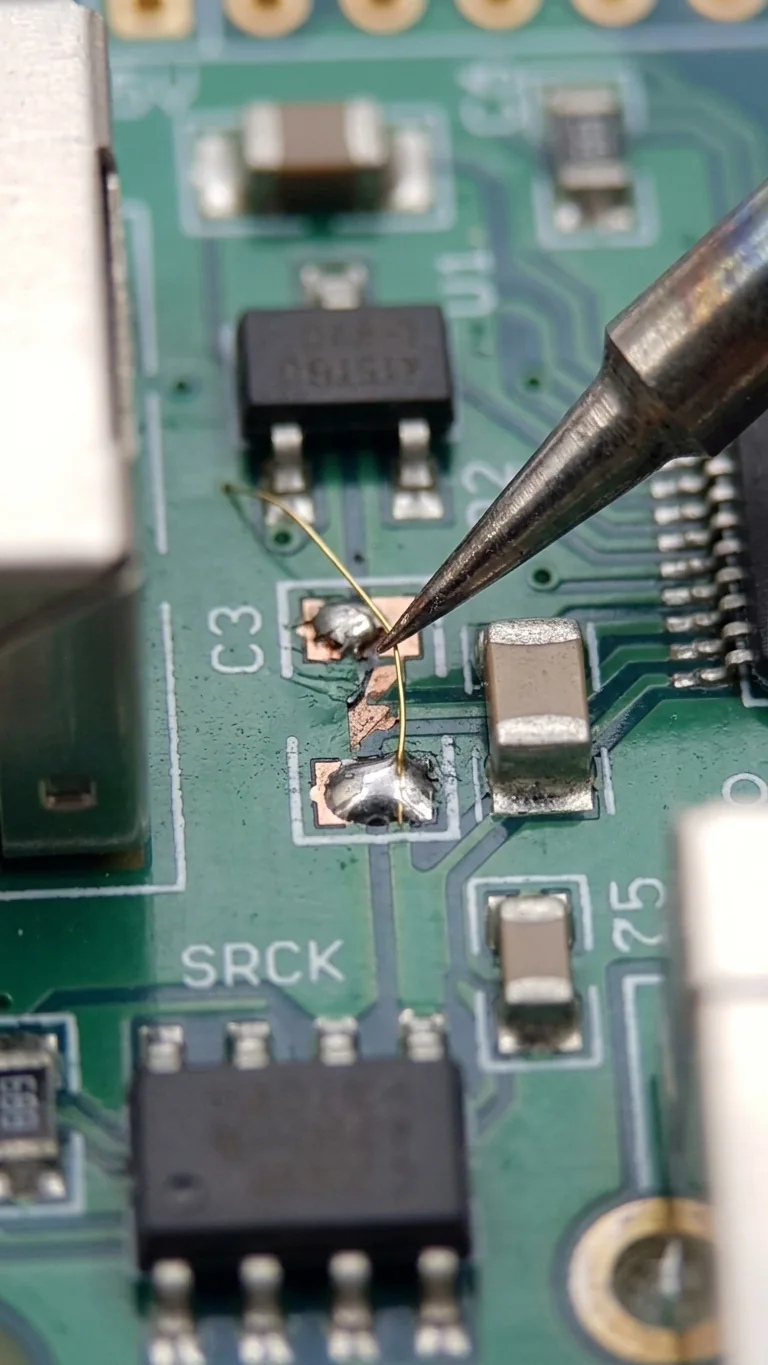
Inspection Image (Figure 3): High-magnification microscope view showing the repair operation. Removed the shorted 0805 capacitor and found that the copper trace beneath it had overheated and lifted.
Trace Reconstruction: Manually reconstructed the lifted trace using fine gold wire and a micro-soldering tip to restore circuit continuity.
Component Replacement: Placed a new 10μF 0805 capacitor across the clean pad and the end of the reconstructed trace for final soldering.
3. Test Records
A current-limited low-voltage injection test may be used on the isolated rail after its normal voltage and polarity are confirmed. Thermal imaging, freeze spray, or voltage-drop probing can then help narrow the heat-producing branch.
Static Resistance Measurement: Resistance between the 5V power rail and ground returned to a normal range (several kilohms) instead of 0 Ω.
Power-On Monitoring: Gradually increased supply voltage to 5V. Current draw stabilized within normal operating limits (≈ 350 mA).
4. Final Results
Reassembled the repaired circuit board back into its multi-layer stack structure.
-
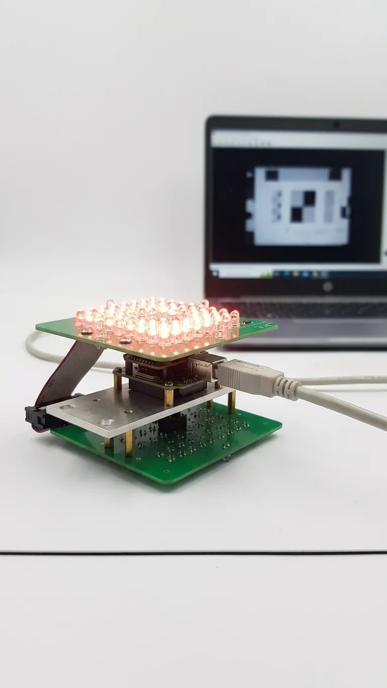
Final Result Image (Figure 4): Shows the fully reassembled unit operating under test:
-
LED Illumination Test: All 64 LEDs in the 8×8 IR array illuminated correctly.
-
Camera Functionality Test: The laptop screen displays a clear live image feed captured by the 5MP camera sensor, confirming complete functional restoration.
-
Related Case
Power and Charging · Power PCB Repair
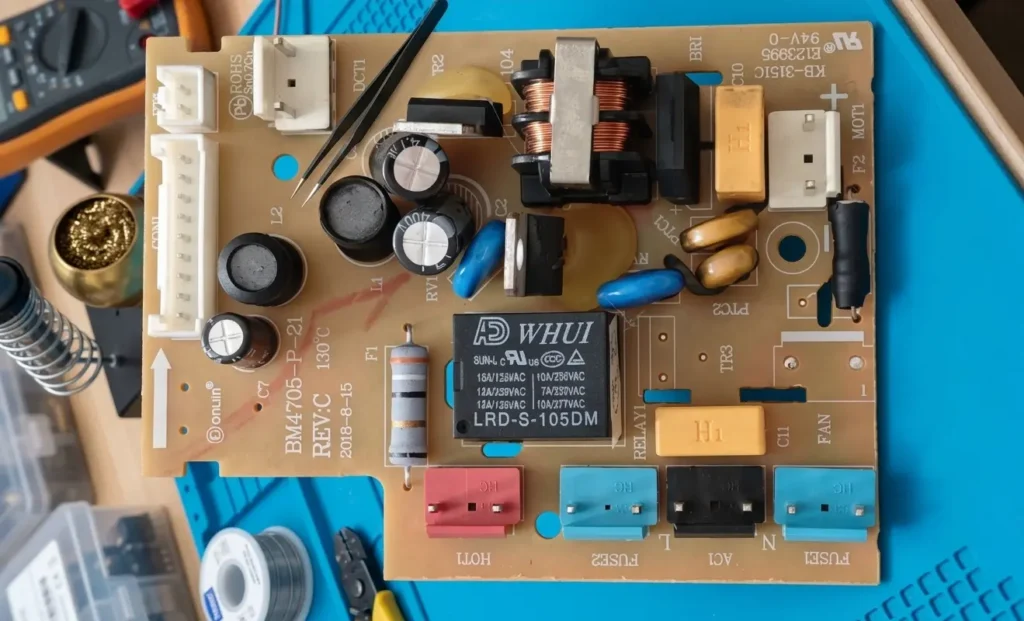
Donlim Bread Maker Power Board (BM4705-P-21) Repair
Fix intermittent motor shutdown on the Donlim bread maker power board (BM4705-P-21) with this step-by-step diagnostic and relay replacement guide.
View case study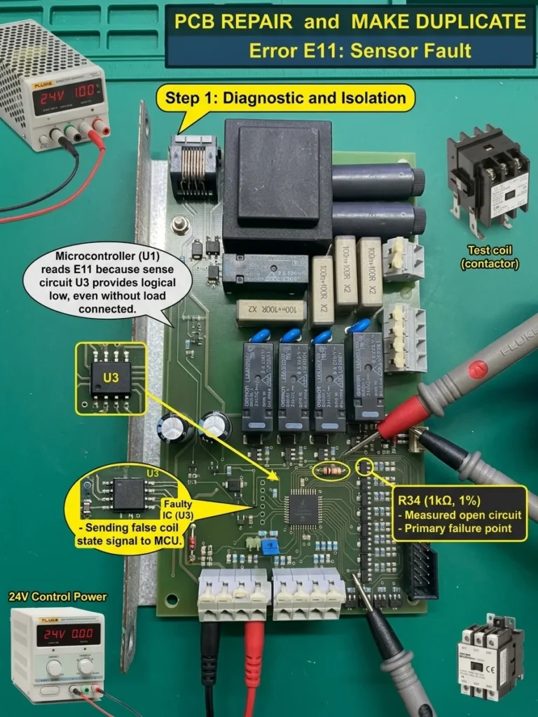
Industrial Control · Control Board Assessment
E11 Relay Control Board Assessment and Repair Planning
Assessment plan for a relay control board reporting E11 ‘coil not working’ even when the external coil is not connected.
View case study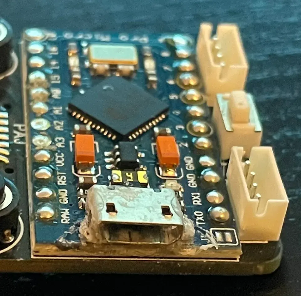
Consumer Electronics · Trace and Pad Repair
Pro Micro USB Port Repair and Trace Bridge
Fix a loose Micro USB port and broken traces on the Pro Micro board with this step-by-step micro-soldering and trace bridging guide.
View case study
Power and Charging · Charging Board Repair
Air Mattress Pump Charging Board Repair
Assessment of a rechargeable air-mattress pump board with reported charging failure and heat damage near the DC input.
View case studyDiscuss your board