
PCB Assessment Case
Pro Micro USB Port Repair and Trace Bridge
Fix a loose Micro USB port and broken traces on the Pro Micro board with this step-by-step micro-soldering and trace bridging guide.
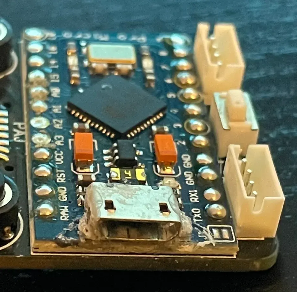
Board typePro Micro compatible board
ApplicationConsumer Electronics
ServiceTrace and Pad Repair
Fault Description
"This is a small microcontroller development board, a Pro Micro compatible board, and I need to resolder the Micro USB port."
Detection Process
-
Initial Fault Analysis: The original board clearly shows a large amount of grey, crystalline residue (likely old flux and oxidized solder) around the outer metal shell of the Micro USB port. The port also looks slightly crooked, meaning it is loose or partly detached from the pads. Your description confirms this.
-
Physical and Microscopic Inspection: Our first step is to confirm the extent of the damage. We need to know if only the metal anchor points have desoldered, or if the more critical data/power pin pads are also damaged (torn).
-
Procedure: We placed the board under a stereo microscope and used fine multimeter probes for physical confirmation.
-
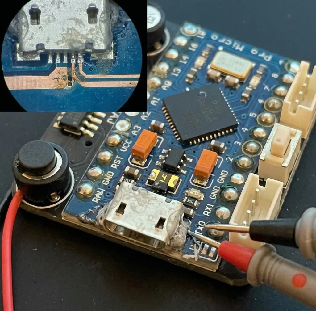
Inspection Analysis:
The red and black multimeter probes test continuity at the edge of the USB port, confirming an unstable connection. The key insert at the top left shows a microscopic view under the port. It reveals severe oxidation and cold joints on the metal shell anchor points (pads #1, #2, and #4), and shows that the PCB copper trace for a critical central data signal pin (D+/D-) is broken and slightly lifted.
Diagnostic Conclusion: This is not a simple resoldering job. It is a complex Level-2 repair involving pad repair and micro-trace bridging.
2. Repair Measures
Based on the inspection results, standard soldering iron work cannot solve the problem. We must use precision micro-welding techniques.
-
Pre-treatment:
-
First, we removed the port completely from the board and cleaned away all old flux, oxidized solder, and dirt.
-
Under the microscope, we used a precision tool to scrape away the solder mask (green oil) around the broken trace to expose bare copper.
-
-
Core Repair Operations:
-
Repair Broken Trace: Using an extremely fine (e.g., 0.02mm) enameled wire, we performed a micro-bridge weld across both ends of the broken trace. This is a high-difficulty precision task.
-
Pad Reconstruction: After fixing the trace, we applied UV-curable solder mask (green oil) to cover and secure the fine wire, leaving only the required pad areas open.
-
Reinstall Port: We placed a cleaned or brand-new Micro USB port in position, using a precision micro hot air gun and high-quality mid-temperature solder paste to align and solder the 5 signal and power pins. Then, we applied a generous amount of solder to reinforce the metal anchor points for higher mechanical strength.
-
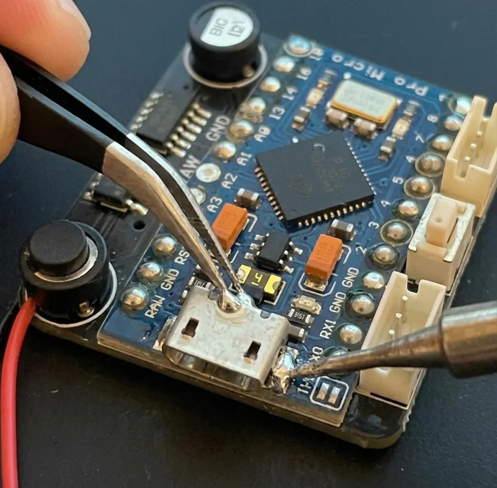
Repair Process Analysis:
All residue is cleaned away, making the area around the port much cleaner. The main image shows the core operation: precision tweezers hold the port firmly in place, and a micro soldering tip precisely melts bright, lead-free solder wire onto the signal pins. The broken trace from Figure 1 is being bridged dynamically. All board labels and surrounding components (like the orange capacitors) remain completely unaffected.
3. Testing and Final Result
After completing the repair, strict testing is required.
-
Mechanical Strength Test: Gently plug and unplug a USB cable to ensure the port is solid with no signs of looseness.
-
Electrical Performance Test:
-
Use a USB tester to check voltage (5V) and current (normal standby current).
-
Connect the board to a computer to confirm it is recognized correctly as an “Arduino Pro Micro” device.
-
Upload a simple “Blink” example program to verify data transfer and downloading functions.
-
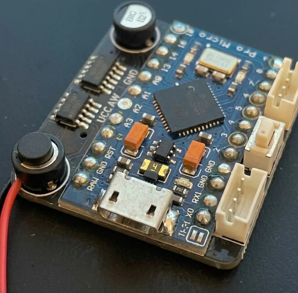
Final Result Analysis:
Perfect Soldering Quality: The Micro USB port is perfectly aligned. All five signal pins feature bright, full, and independent solder fillets with zero bridging.
Reinforced Anchors: The metal shell anchor points on both sides are firmly secured to the main board with full solder joints to provide strong mechanical strength against future damage.
Clean Finish: All old residue and flux were cleaned away with isopropyl alcohol, restoring the board surface to look like new.
Final Conclusion: The Micro USB port on this small PCB has been successfully repaired. The loose connection and broken data trace are fixed, and the mechanical structure is reinforced. Testing confirms full functional recovery for stable use.
Related Case

Power and Charging · Charging Board Repair
Air Mattress Pump Charging Board Repair
Assessment of a rechargeable air-mattress pump board with reported charging failure and heat damage near the DC input.
View case study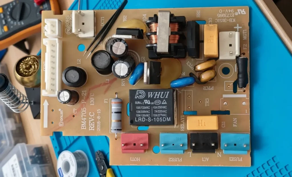
Power and Charging · Power PCB Repair
Donlim Bread Maker Power Board (BM4705-P-21) Repair
Fix intermittent motor shutdown on the Donlim bread maker power board (BM4705-P-21) with this step-by-step diagnostic and relay replacement guide.
View case study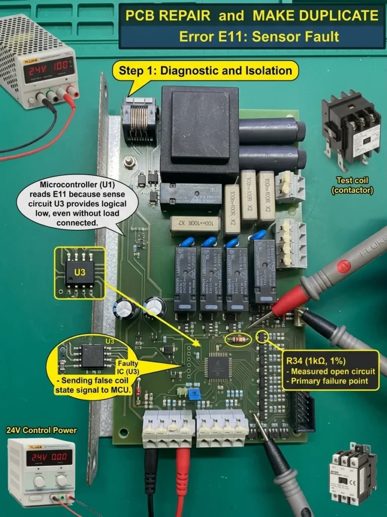
Industrial Control · Control Board Assessment
E11 Relay Control Board Assessment and Repair Planning
Assessment plan for a relay control board reporting E11 ‘coil not working’ even when the external coil is not connected.
View case study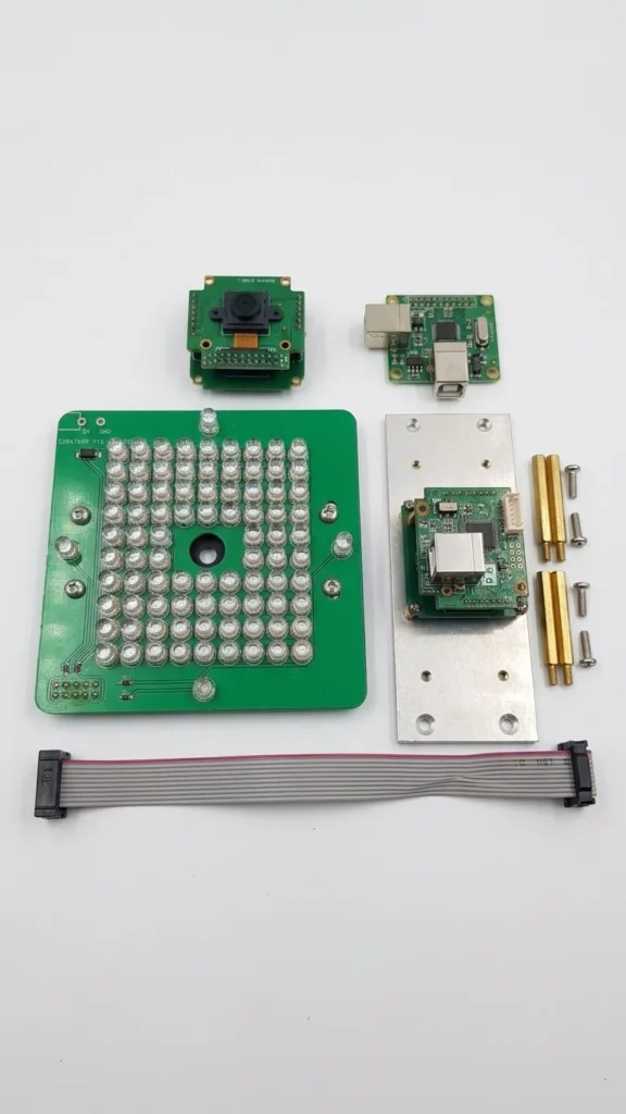
Automotive Service Equipment · Short-Circuit Diagnosis
3D Wheel Alignment Camera Board Short-Circuit Repair
Board-level assessment plan for a short-circuited 5MP camera module from an SM-V2 3D wheel-alignment system.
View case studyDiscuss your board