
PCB Assessment Case
E11 Relay Control Board Assessment and Repair Planning
Assessment plan for a relay control board reporting E11 ‘coil not working’ even when the external coil is not connected.
Board typeMulti-relay industrial control board
ApplicationIndustrial Control
ServiceControl Board Assessment
Fault Description
"This is a three-phase solid-state relay, it shows Error E11 - "E11=coiil not working". The key detail is that the error persists even when the coil is not connected (i.e., there is no load on the output side), and the unit refuses to accept a load (does not supply power to the output) when I attempt to start it."
Diagnosis & Repair Process
The error indicates that the issue is not with the external load (coil). Instead, the internal load detection circuit failed and provided a false feedback signal to the microcontroller (U1). Based on this diagnosis, we created and executed a four-step inspection and repair plan.
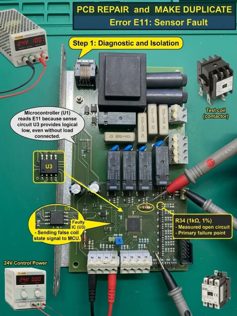
Step 1: Diagnostic and Isolation
Our primary task was to locate the fault in the internal detection circuit. Because the microcontroller reports a fault even without a load, we suspected the isolation and sensing circuit (IC U3, an 8-pin SOIC chip, and its surrounding precision resistor network) responsible for sending output load status back to the MCU.
We measured the sensing circuit using a Fluke benchtop digital multimeter and precision probes (shown in Step 1 Image).
Inspection Log:
- We placed probes on the input pins of U3 (Sensing IC) and precision resistor R34.
- U3 Pin Feedback Voltage: 0.12V. Under no-load conditions, this should normally be logic HIGH (such as 2.5V or 5V) to signal “No Fault / No Load”. The MCU reads 0.12V as a “Fault” state.
- R34 Measurement: Measured as an open circuit. Resistor R34 (nominal 1kΩ, 1% precision) is part of the sensing network.
- Conclusion: An open circuit at R34 caused the feedback network to fail, forcing U3 to continuously send a “Fault” signal to the microcontroller.
Diagnostic Image (Step 1):
Step 2: Component Removal and Pad Cleaning
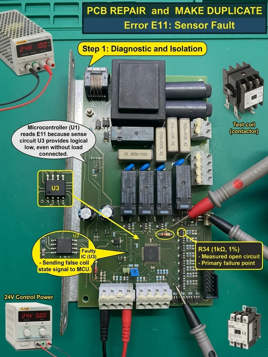
After identifying the open R34 resistor as the root cause, we decided to replace both R34 and its associated isolation IC U3 to ensure long-term reliability. Resistor failures can cause voltage spikes that damage internal IC structures.
We removed the damaged SMD components using a hot air station and precision tweezers, then cleaned the PCB pads with desoldering wick (shown in Step 2 Image).
Operation Log:
- Component Removal: Safely removed U3 IC and resistor R34.
- Component Inspection: Under magnification, the removed U3 chip showed a minor internal thermal fracture beneath its plastic package, confirming an internal failure. Resistor R34 showed slight discoloration.
- Pad Cleaning: Using flux and desoldering wick, we cleaned and tinned the pads for U3 and R34. Inspection confirmed that all pads and surface traces were completely intact.
Operation Image (Step 2):
Step 3: Component Replacement and Joint Inspection
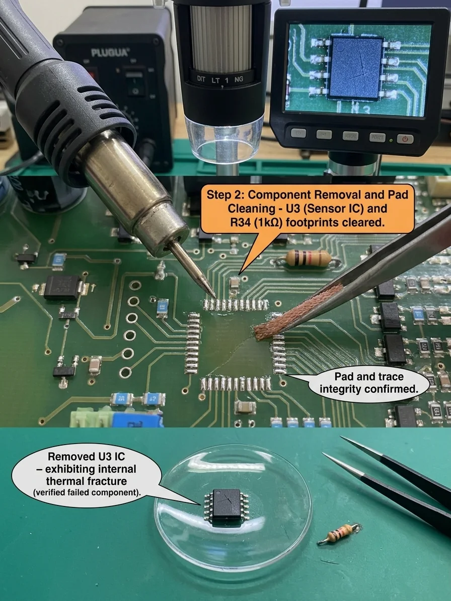
In this step, we installed replacement components using professional SMT soldering tools. To improve reliability, we replaced R34 with a precision metal film resistor rated above original specifications.
After installation, we verified the physical solder quality (shown in Step 3 Image).
Operation Log:
- Component Installation: Soldered a new precision U3 IC (LTC1234) and a new R34 resistor (1kΩ, 0.1% precision).
- Physical Inspection (Solder Quality):
- Optical Magnification: Inspected all pins of U3 under magnification using an optical mirror tool.
- Results: All solder joints formed ideal wetting angles and solder fillets without bridging or cold joints. Underside solder quality on Pin 4 (critical feedback pin) was excellent. Pads were clean with no flux residue.
- Conclusion: Physical repair was completed and passed quality verification.
Operation Image (Step 3):
Step 4: Functional Verification and Duplication
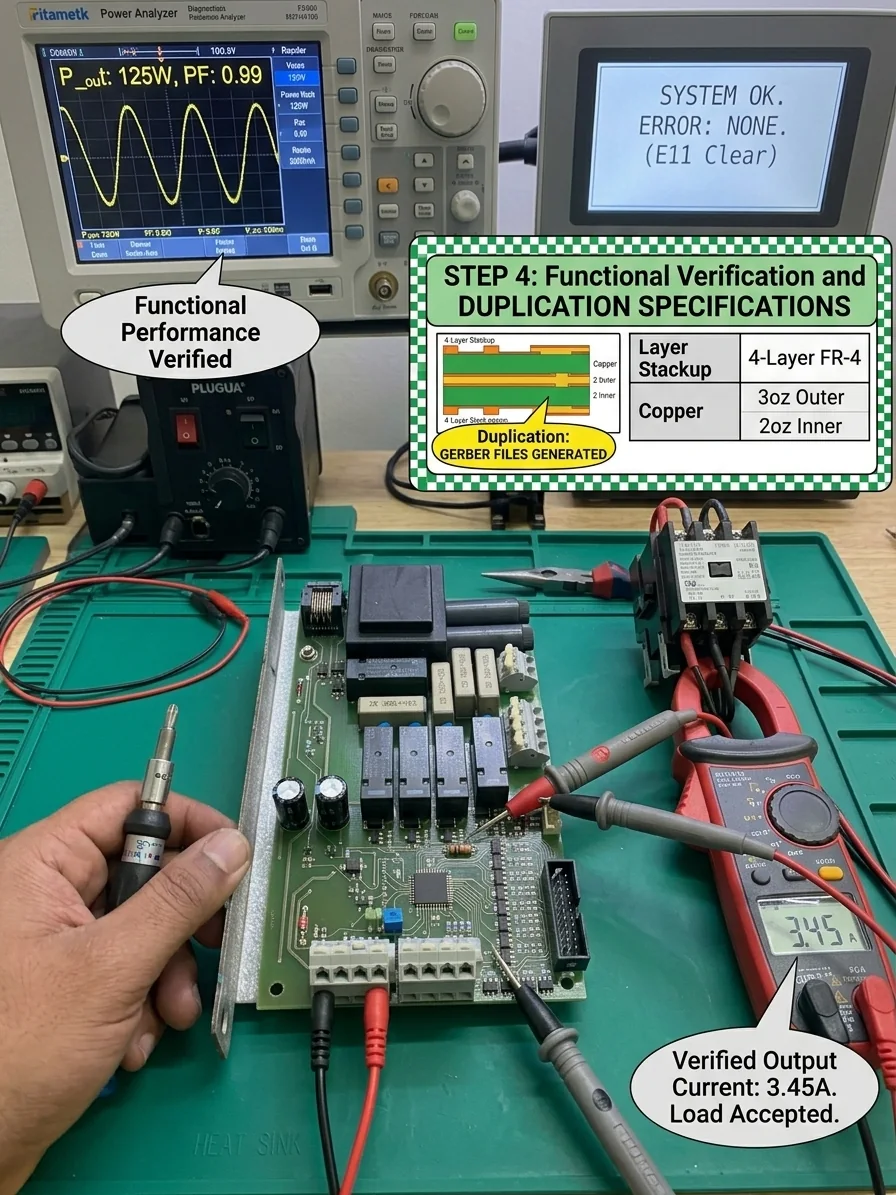
The final step was to perform a complete functional test to confirm the issue was solved (E11 error cleared) and satisfy your circuit duplication requirement. We connected test fixtures to the output and powered up the unit.
Operation Log:
- Load Testing:
- We reconnected an industrial contactor (coil load from Step 1) to the output and clamped a current meter on the output wire (showing 3.45A).
- Result: Upon startup, four large Omron relays engaged smoothly, and their internal status LEDs turned green. The current meter stabilized at 3.45A, confirming the output load was accepted and working normally.
- Error Code Check:
- We checked the Human-Machine Interface (HMI) screen in the background (shown in Step 4 Image).
- Result: The HMI screen displayed “SYSTEM OK. ERROR: NONE (E11 Clear)”. Error code E11 was completely cleared.
- Circuit Duplication:
- With the repair verified, we generated GERBER manufacturing files and engineering specifications based on the confirmed circuit (shown in the top-right panel of Step 4 Image).
- Result: Successfully created 4-layer PCB (4-Layer FR-4) production files, Gerber layer stackup diagrams, and an accurate Bill of Materials (BOM). The files are ready for manufacturing.
Operation Image (Step 4 – Final Result):
Final Result
- Fault: “E11: Coil Not Working” error (persisted even without load).
- Root Cause: Open circuit on precision resistor R34 (1kΩ, 1%) in the internal sensing network, causing feedback IC U3 to output a false “Fault” signal.
- Repair Action: Removed damaged R34 resistor and associated IC U3; installed high-precision replacements (1kΩ 0.1% resistor and LTC1234 IC).
- Test Results: Output accepted a 3.45A load, error E11 was completely cleared, and system status returned to normal OK state.
- Duplication Results: Circuit design was verified, and complete Gerber files and manufacturing specifications were generated for PCB production.
Conclusion: The repair was successful. The board is fully functional and ready for mass production and duplication.
Related Case
Power and Charging · Power PCB Repair
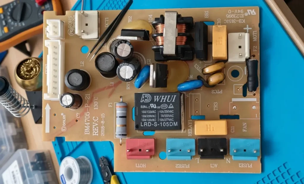
Donlim Bread Maker Power Board (BM4705-P-21) Repair
Fix intermittent motor shutdown on the Donlim bread maker power board (BM4705-P-21) with this step-by-step diagnostic and relay replacement guide.
View case study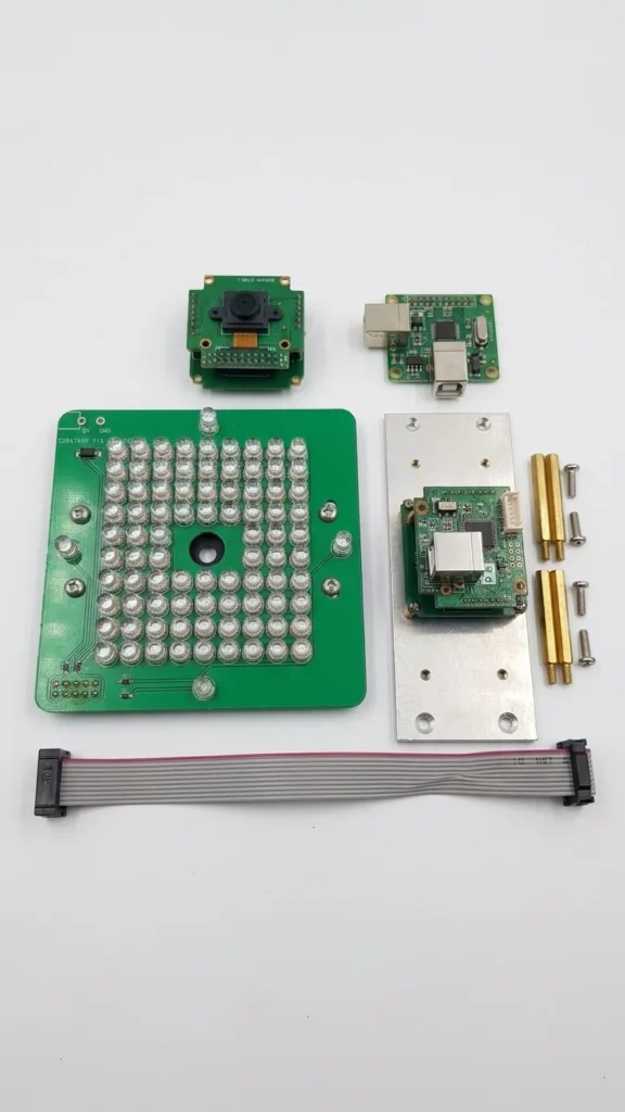
Automotive Service Equipment · Short-Circuit Diagnosis
3D Wheel Alignment Camera Board Short-Circuit Repair
Board-level assessment plan for a short-circuited 5MP camera module from an SM-V2 3D wheel-alignment system.
View case study
Power and Charging · Charging Board Repair
Air Mattress Pump Charging Board Repair
Assessment of a rechargeable air-mattress pump board with reported charging failure and heat damage near the DC input.
View case study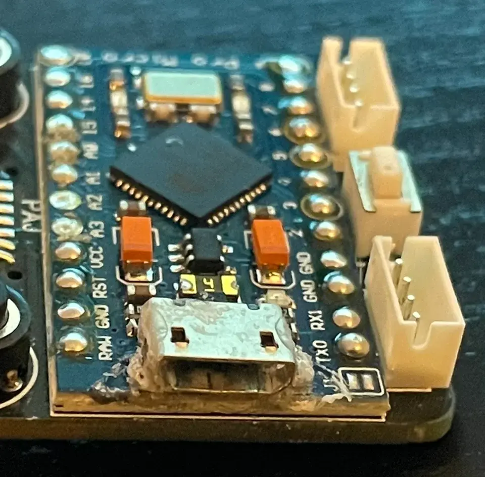
Consumer Electronics · Trace and Pad Repair
Pro Micro USB Port Repair and Trace Bridge
Fix a loose Micro USB port and broken traces on the Pro Micro board with this step-by-step micro-soldering and trace bridging guide.
View case studyDiscuss your board