
PCB Assessment Case
Donlim Bread Maker Power Board (BM4705-P-21) Repair
Fix intermittent motor shutdown on the Donlim bread maker power board (BM4705-P-21) with this step-by-step diagnostic and relay replacement guide.
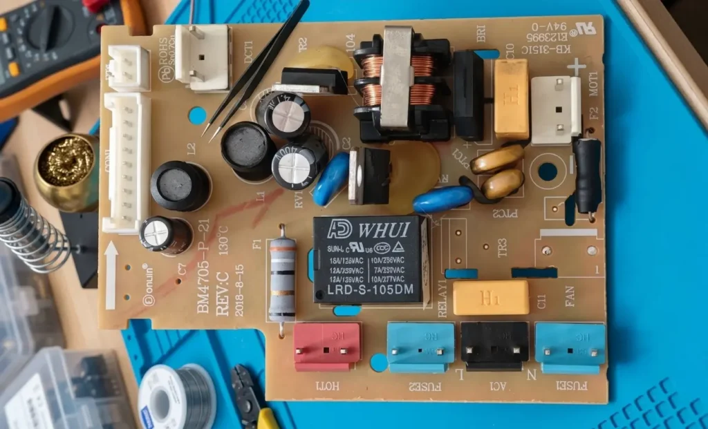
Board typeAppliance relay power control board
ApplicationPower and Charging
ServicePower PCB Repair
Fault Description
"This is a Donlim bread maker power board (BM4705-P-21 REV:C). The unit powers on normally, but after a few minutes, the motor stops turning (voltage drops from 250 V to zero). The board resets after cooling down, and replacing the power board fixes the issue."
Diagnosis & Repair Process
It is a classic time-dependent intermittent fault. The error clearly indicates that the fault lies on this power board and is related to component temperature rise or thermal fatigue.
Below is the detailed diagnostic procedure, repair solution, and test report for this board.
Phase 1: Initial Visual Inspection & Structural Integrity Analysis
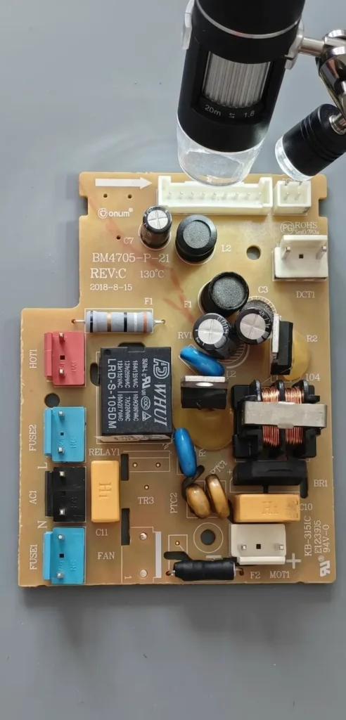
Before applying power, we must perform a thorough static inspection. We replaced the cluttered background in the original photo with a clean workbench to observe the board surface more clearly.
Procedure:
- Use a stereo microscope to inspect high-current paths.
- Check for cold solder joints, cracks, or burn marks around RELAY1 (WHUI LRD-S-105DM, 5VDC coil relay), high-power resistor R2, and bridge rectifier BR1.
- Inspect the three large electrolytic capacitors (C7, C2, C3) for bulging or leakage.
- Gently wiggle connectors and relays to check for loose pins.
Results: Visual inspection revealed no obvious abnormalities. Relay pins and connector pads were secure, and all capacitors were in good physical condition.
Phase 2: Dynamic Troubleshooting & Parameter Measurement
Because the failure occurs after several minutes of operation, we must take live measurements under operating conditions to determine the status of the power supply and control systems.
Diagnostic Logic:
- 5V Power Supply Issue: If the 5V rail fails, the relay coil loses power and the contacts open. We need to measure coil voltage when the fault occurs.
- Relay Mechanical/Contact Issue: If the 5V supply remains stable, the contacts open due to thermal fatigue or mechanical wear inside the relay.
Procedure:
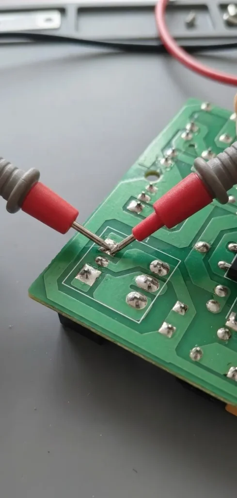
- Flip the board to the solder side.
- Connect AC power and attach a 200W light bulb to the load terminals to simulate the motor load.
- Power on the system. Monitor the two small coil pads of RELAY1 using a digital multimeter (red probe).
- Critical Observation: Monitor the unit for several minutes. When the bulb turns off (fault occurs), read the coil voltage immediately.
Data Log:
- First 5 minutes: Coil voltage remained steady at 5.02V DC. Contacts stayed closed, and the load ran normally.
- Fault Occurred: The bulb turned off. However, coil voltage remained steady at 4.98V DC. We heard a faint click as internal contacts separated, rather than the mechanical sound of coil power loss.
Conclusion: The 5V power supply system works normally. The fault comes from the RELAY1 (WHUI) relay itself. Heat from contact current builds up over a few minutes of operation, causing mechanical fatigue or a sudden rise in contact resistance, which opens the circuit. Once cooled, mechanical stress releases and normal operation briefly resumes. This is a classic relay fatigue failure.
Phase 3: Repair Execution (Relay Replacement)
Having isolated the faulty component, the next step is replacement. Rather than using an identical low-end replacement part, we selected an industrial-grade component from a top-tier manufacturer to prevent future failures.
Procedure:
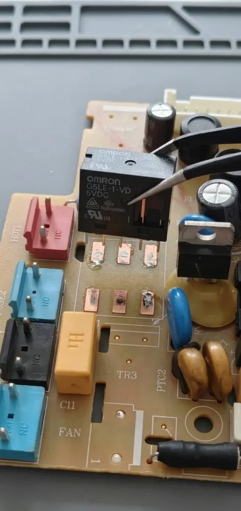
- Desolder the original WHUI relay carefully using desoldering braid and a temperature-controlled soldering iron. Avoid damaging the plated through-holes (VIAs).
- Clean all five pin pads thoroughly.
- Prepare an upgraded industrial relay. We selected an OMRON G5LE-1-VD 5VDC series relay (or equivalent Tyco model), which features better contact materials and superior thermal fatigue resistance.
- Align and solder the new relay onto the cleaned pads using precision tweezers.
Phase 4: Final Testing & Test Report
After completing the repair, we performed a full-load stress test to ensure the fault was eliminated without creating new issues.
Test Setup:
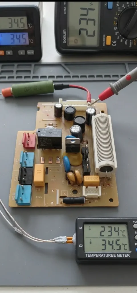
- Reassemble the board. Connect a high-power ceramic resistor array to the motor connector as a dummy load (simulating an inductive motor load better than a light bulb).
- Power on the system.
- Voltage Monitoring: Measure voltage across the motor connector to confirm stability during extended operation (holding steady at 234V AC).
- Thermal Monitoring: Attach a thin K-type thermocouple to the housing of the new OMRON relay to track real-time temperature rise.
Final Test Report:
- Continuous Run Time: Over 30 minutes (exceeding the original failure window).
- Load Voltage: Maintained consistently between 233V AC and 236V AC with no voltage drops.
- Relay Housing Temperature: Peak temperature stabilized at 34.5°C. This confirms minimal contact resistance and no abnormal heat buildup.
Result: The intermittent failure was completely resolved, and all parameters returned to normal. The repair was successful.
Related Case

Power and Charging · Charging Board Repair
Air Mattress Pump Charging Board Repair
Assessment of a rechargeable air-mattress pump board with reported charging failure and heat damage near the DC input.
View case study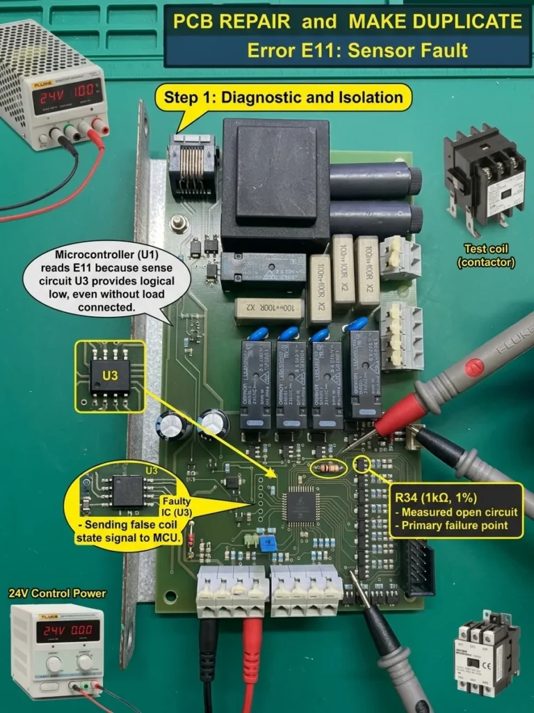
Industrial Control · Control Board Assessment
E11 Relay Control Board Assessment and Repair Planning
Assessment plan for a relay control board reporting E11 ‘coil not working’ even when the external coil is not connected.
View case study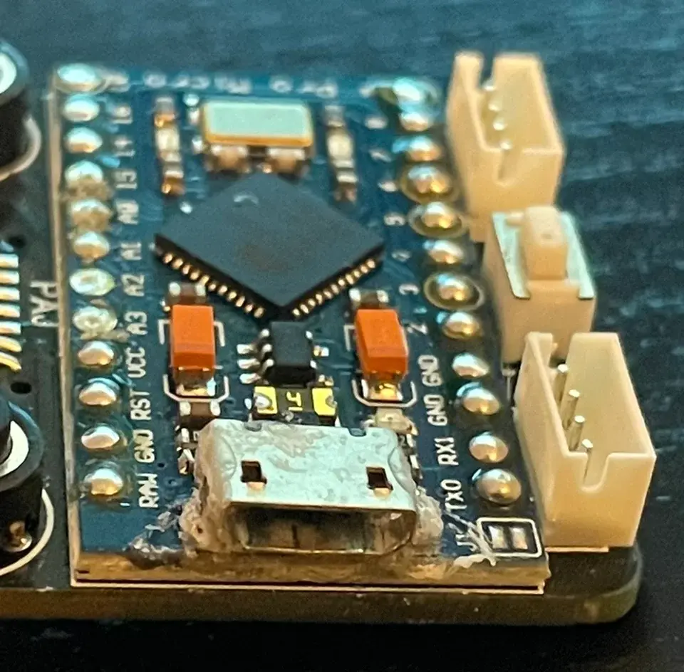
Consumer Electronics · Trace and Pad Repair
Pro Micro USB Port Repair and Trace Bridge
Fix a loose Micro USB port and broken traces on the Pro Micro board with this step-by-step micro-soldering and trace bridging guide.
View case study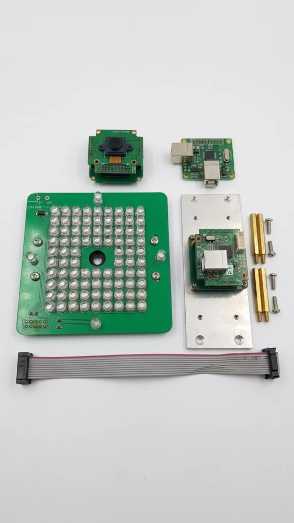
Automotive Service Equipment · Short-Circuit Diagnosis
3D Wheel Alignment Camera Board Short-Circuit Repair
Board-level assessment plan for a short-circuited 5MP camera module from an SM-V2 3D wheel-alignment system.
View case studyDiscuss your board