
PCB Assessment Case
Defibrillator AC-DC Power Module Short-Circuit Repair
The power module would not start, produced no DC output, and operated the upstream protection. Diagnosis localized the short to the secondary rectifier stage before matching-rated devices were replaced.
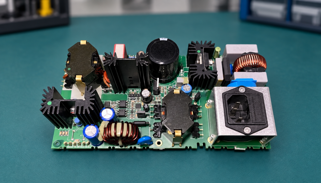
Board typeHigh-power AC-DC power supply module
ApplicationMedical Equipment
ServiceComponent Replacement, Power Circuit Repair
Fault Description
"Our high-power AC-DC switching power supply module completely stopped working and provides zero DC output voltage. Every time we try to turn the machine on, it instantly trips our facility's circuit breaker and blows the main protection fuse. We are unable to boot the servo driver unit at all."
Detection Process
-
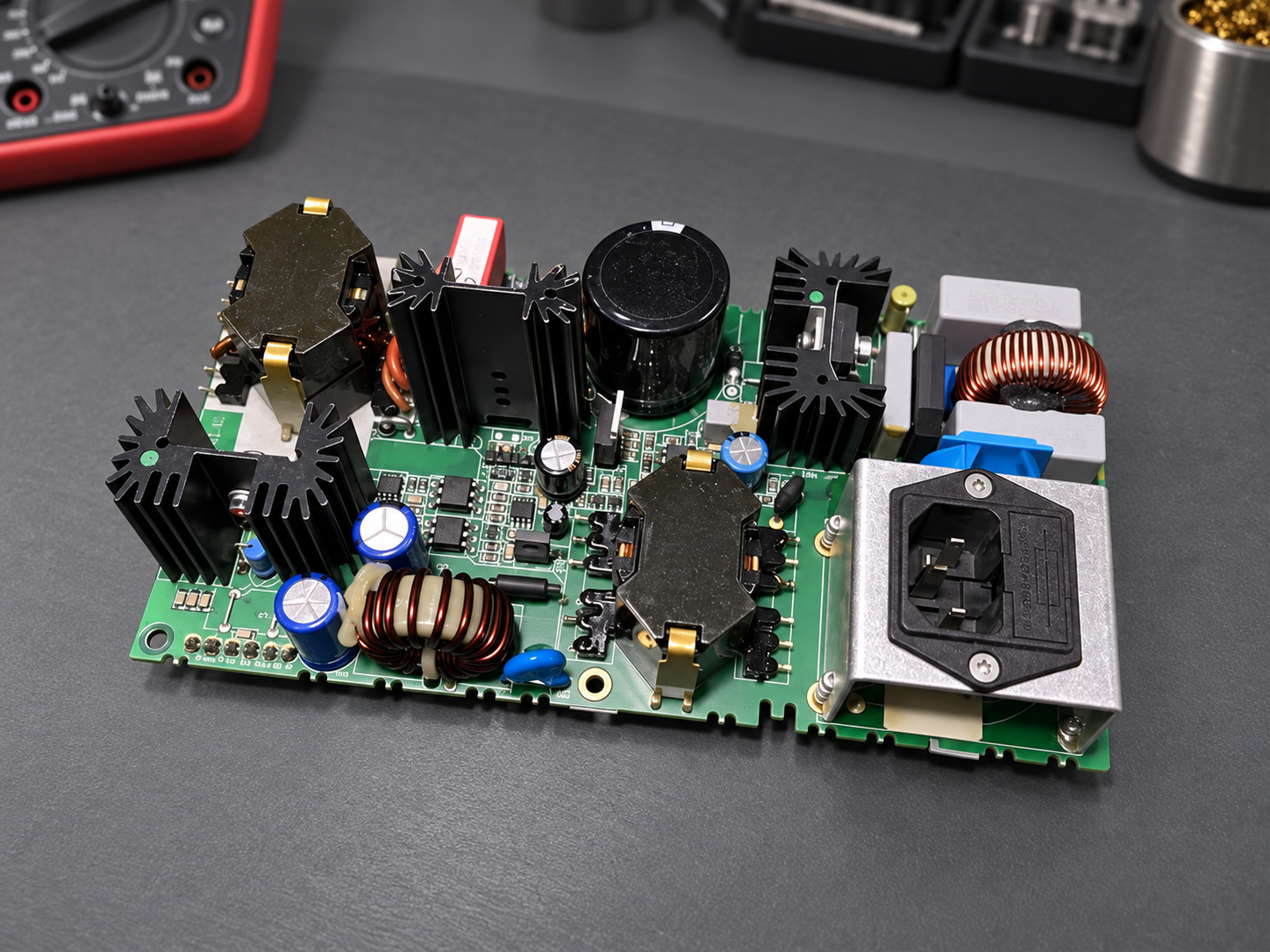
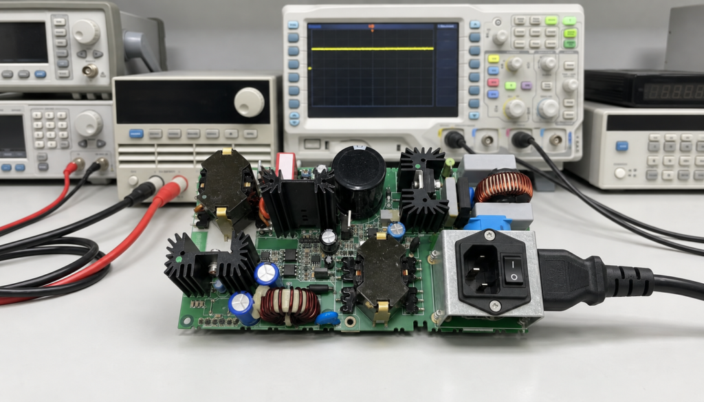
Visual Inspection: Carefully inspected the entire circuit board. Although the layout of components (transformers, inductors, large heat sinks, electrolytic capacitors) was compact, there were no obvious signs of bulging, burning, charring, or PCB carbonization. The EMI filter area and PFC stage appeared normal.
-
Preliminary Measurement (Static Measurement):
-
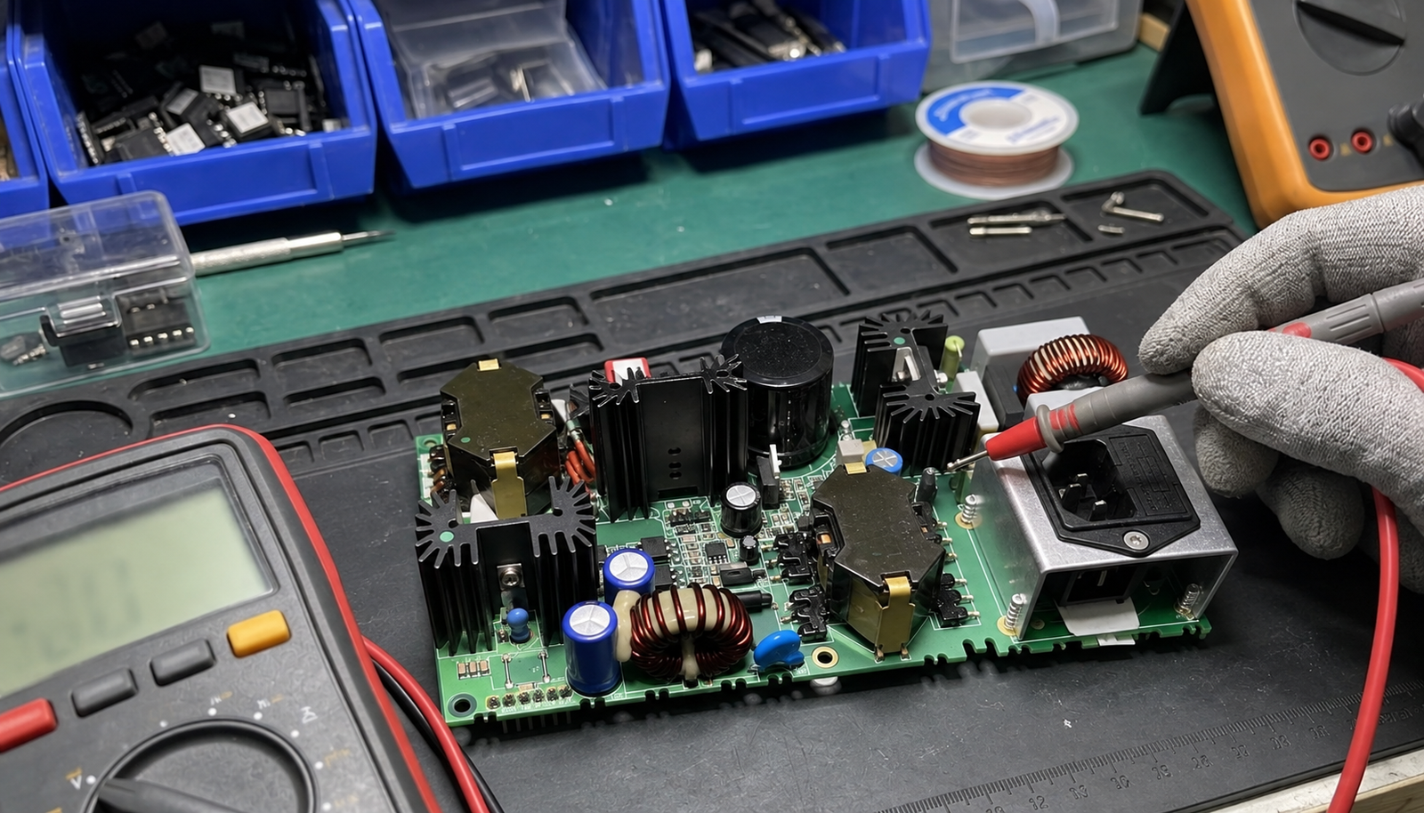
PFC Stage Check: Measured the resistance across the main filter capacitor (large black capacitor in the center) using a multimeter. The reading was normal, ruling out a direct short circuit in the PFC stage.
-
Secondary Rectification Check (Key Step): Shifted focus to the secondary side of the transformer (12320063-2). Since the fault tripped upstream protection, breakdown of the secondary rectifier diodes was the most likely cause. Set the multimeter to diode/resistance mode and measured the Schottky diodes located under the middle and left heat sinks.
-
Detection Result: When measuring a TO-220 packaged rectifier diode (e.g., D4, D5) mounted under the middle heat sink, the multimeter displayed a low resistance near zero (0.01 Ω, bidirectional continuity). This confirmed a severe short circuit on the secondary output side.
-
Repair Process
-
Component Removal (Key Step):
-
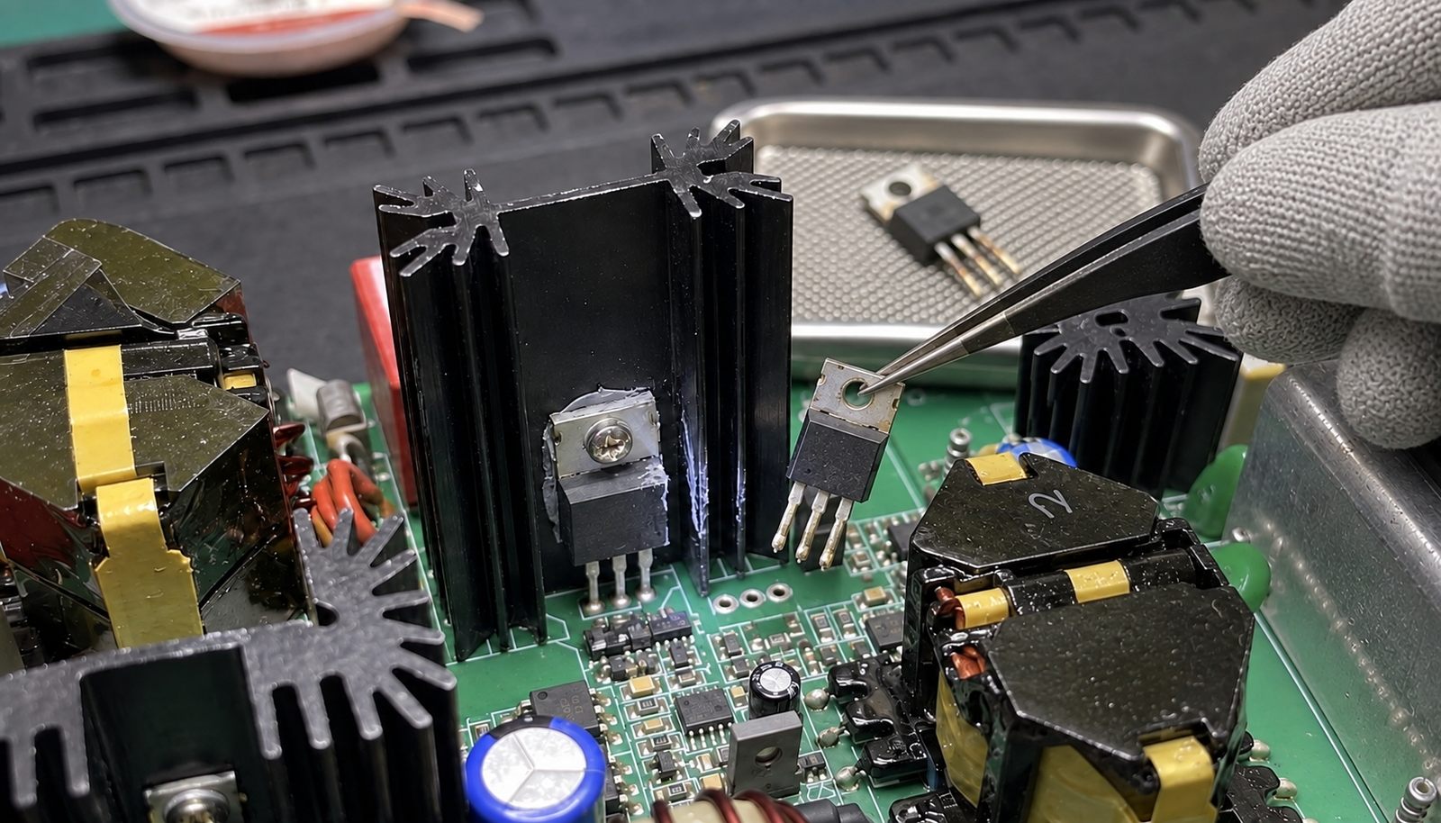
The faulty components were TO-220 Schottky rectifier diodes located beneath the large heat sink. Because they were mounted tightly against the heat sink, a standard soldering iron could not remove them quickly.
-
Procedure: Loosened the heat sink mounting screws slightly to gain clearance. Using a high-power desoldering station (≈ 80W) paired with a solder sucker, melted and cleared solder from the pins of the two damaged diodes (e.g., model MBR20100CT) one by one. Heating time and pressure were carefully controlled to prevent damaging PCB through-holes and pads.
-
Removal Result: Successfully desoldered the two shorted Schottky diodes. Thermal grease residue was visible on the heat sink surface and component pins.
-
-
Component Replacement:
-
Cleaned the solder pads and selected two new Schottky diodes of identical specifications (MBR20100CT).
-
Applied fresh thermal silicone grease to the metal backplates of the components to ensure proper heat dissipation.
-
Reinserted the components into the PCB and soldered them securely.
-
Pad Inspection: Due to precise operation, the solder pads and surface traces suffered no damage.
-
Test Records and Results
- Static Re-measurement: After replacing the components, re-measured the resistance at the secondary output side with the multimeter. The reading returned to normal (non-shorted state). Inspected adjacent electrolytic capacitors; no associated damage was found.
-
Power-On Test (Key Step):
- Connected the power supply board to an isolation transformer for safety and powered it via an adjustable AC source.
- Connected the AC input terminals, and attached an electronic load along with an oscilloscope probe to the DC output terminals.
- Gradually increased the AC voltage while monitoring the output voltage.
- Test Result: When AC reached the rated voltage (110V/220V), the power supply started successfully. The DC output voltage (±24VDC) stabilized, and the oscilloscope showed extremely low ripple (<100 mVp-p).
- Load Testing: Gradually increased the electronic load up to rated power (+24VDC, 5A, 121.0W). The power supply operated stably without abnormal temperature rise or noise.
- Final Outcome: The AC-DC power module passed comprehensive load testing, confirming a successful repair before being returned to the customer.
Scope and Limitations
This result applies only to the repaired AC-DC module under the recorded bench conditions. It does not cover the complete defibrillator, delivered-energy accuracy, charging time, synchronization, ECG functions, battery operation, insulation, leakage current, electrical safety, calibration, or return-to-service approval.
Related Case
Power and Charging · Power PCB Repair
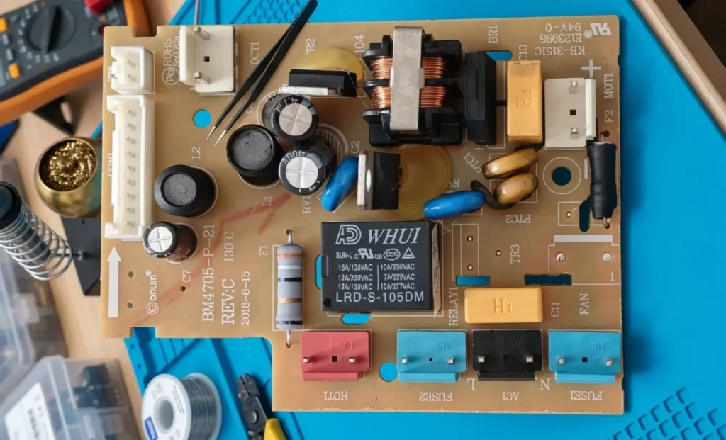
Donlim Bread Maker Power Board (BM4705-P-21) Repair
Fix intermittent motor shutdown on the Donlim bread maker power board (BM4705-P-21) with this step-by-step diagnostic and relay replacement guide.
View case study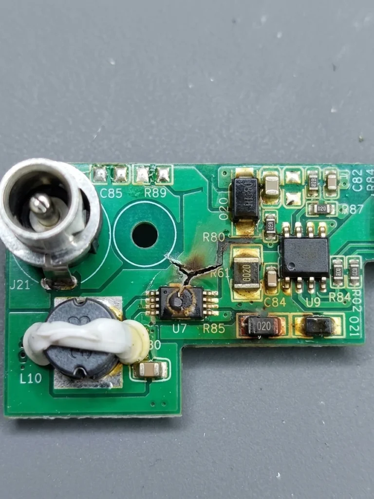
Power and Charging · Charging Board Repair
Air Mattress Pump Charging Board Repair
Assessment of a rechargeable air-mattress pump board with reported charging failure and heat damage near the DC input.
View case study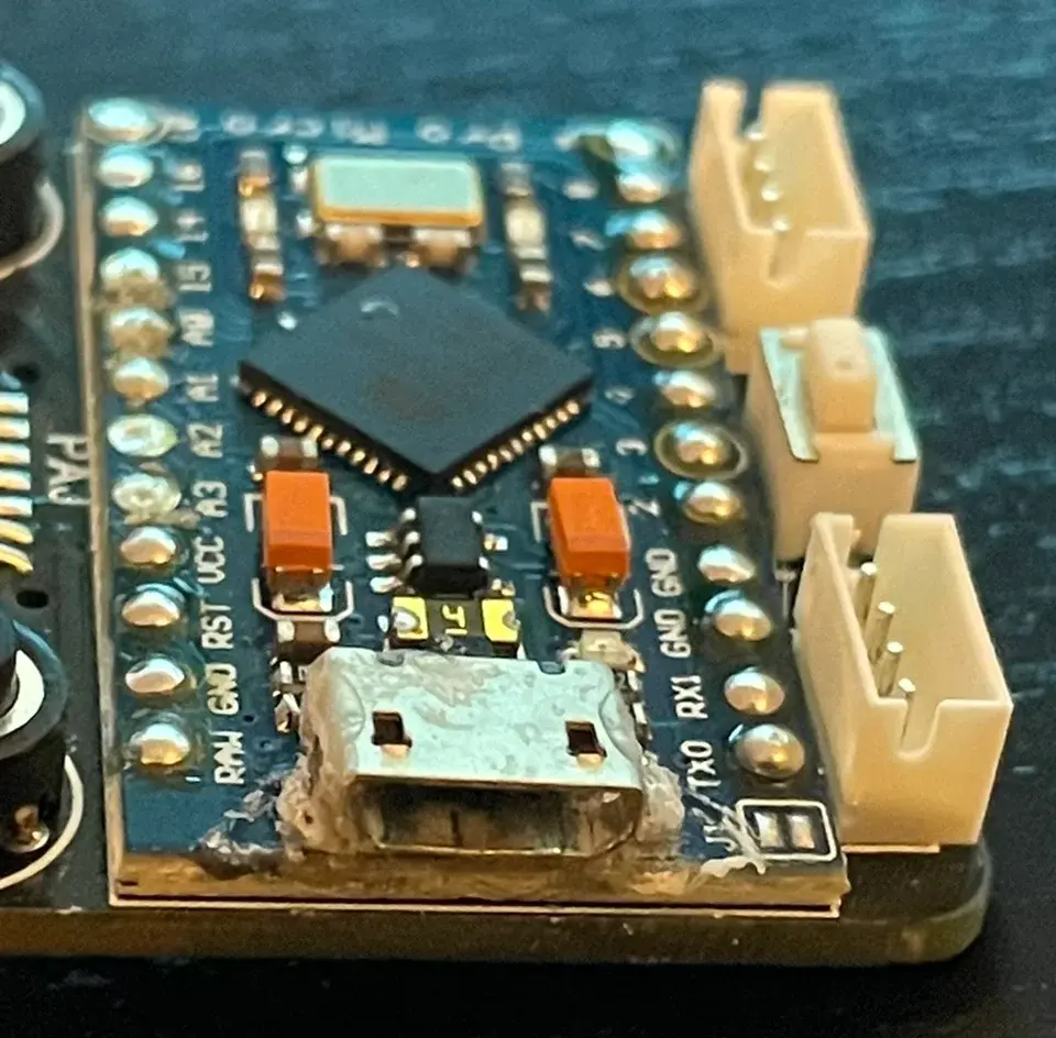
Consumer Electronics · Trace and Pad Repair
Pro Micro USB Port Repair and Trace Bridge
Fix a loose Micro USB port and broken traces on the Pro Micro board with this step-by-step micro-soldering and trace bridging guide.
View case study
Laboratory Equipment · Medical Equipment · Power Circuit Repair · Trace and Pad Repair
Medical Ultrasonic Cleaner Input Filter Board Repair
The cleaner opened its fuse immediately at power-on. Inspection isolated a hard short on the AC input filter board, with a failed common-mode component, carbonized PCB material, and damaged connections.
View case studyDiscuss your board