
PCB Assessment Case
Medical Ultrasonic Cleaner Input Filter Board Repair
The cleaner opened its fuse immediately at power-on. Inspection isolated a hard short on the AC input filter board, with a failed common-mode component, carbonized PCB material, and damaged connections.
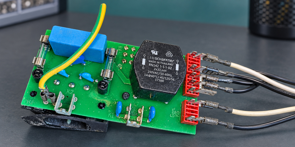 Illustrative reconstruction
Board typeAC input filter and power-entry board
ApplicationLaboratory Equipment, Medical Equipment
ServicePower Circuit Repair, Trace and Pad Repair
Fault Description
”A medical ultrasonic cleaner instantly blew the main fuse upon power-up, leaving the machine completely unresponsive and unable to turn on."
Fault Analysis
This is a classic hard short-circuit fault. After entering through the AC 220V line, power passes through the filter, rectifier bridge, large filter capacitor, and finally reaches the ultrasonic drive circuit. The short circuit was most likely located in the AC input filter, the rectifier bridge itself, or the subsequent power devices (IGBT/MOSFET). We noted that the machine uses a separate input filter sub-board, which provided a great starting point.
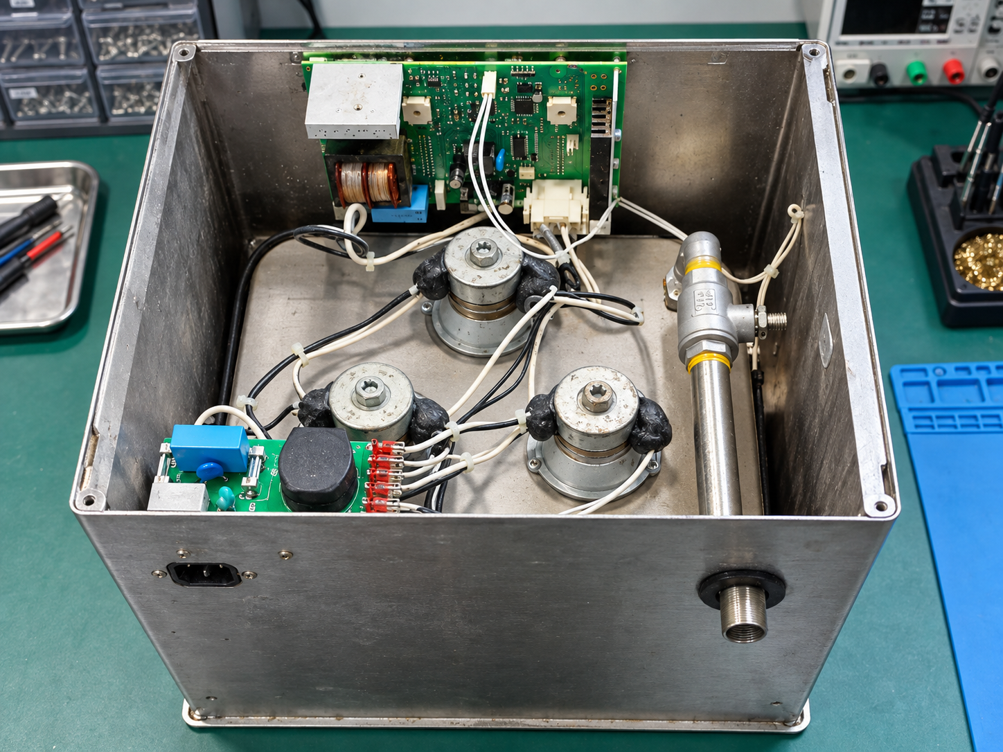
Fault Detection Process
First, we removed this independent power input filter board.
-
Power-Off Measurement: Before replacing any fuse, we had to find the short circuit point. I first used a multimeter set to the resistance range to measure the resistance across the AC input terminals.
-
Locating the Short: As shown in Figure 1, the red and black multimeter probes are directly connected to the AC input side pins of the Schaffner common-mode inductor (the large black square component). The measurement result showed a striking 0.2 Ω. This indicated a severe, nearly direct hard short at the input.
-
This confirmed our inference: the short circuit occurred on the input filter board, causing the fuse to melt instantly. Because there were very few components on this board, the short circuit point was quickly isolated.
Test Steps Table
| Test Point | Measurement Item | Measured Value | Result Analysis |
|---|---|---|---|
| 1 (Power Off) | Resistance between L/N pins at AC input | 0.2 Ω | Confirms a hard short circuit at the input |
| 2 (Power Off) | Resistance across inductor pins after removal | Shorted | Internal breakdown short circuit within the filter component |
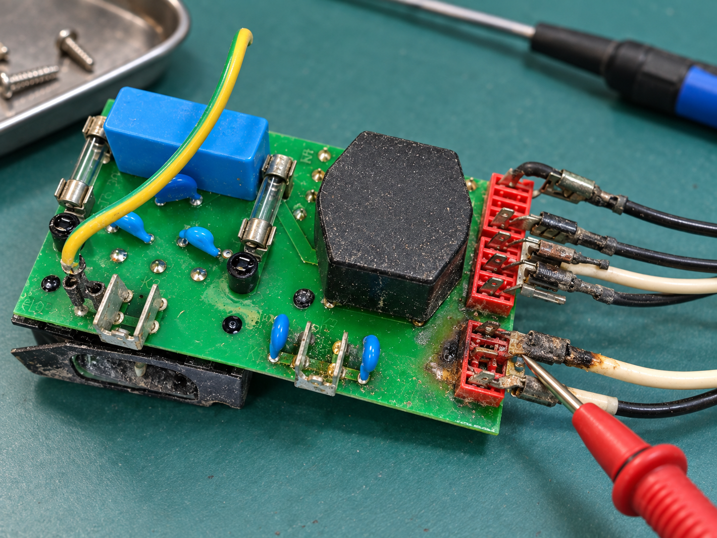
Figure 1: Fault Detection – Input Short Circuit Measurement
The multimeter probes are connected to the AC input side of the Schaffner common-mode inductor on the filter board, displaying a low reading of 0.2 ohms which indicates a severe input short circuit.
Repair Work
After careful troubleshooting, we found that the short circuit point was inside the Schaffner common-mode inductor, where the coils on its AC input side had broken down and shorted. More seriously, due to the excessive short-circuit current, the vias and surface traces on the input board PCB connected to the inductor pins suffered severe carbonization and breakage.
Specific repair steps were as follows:
-
Remove Burned Components: Carefully removed the shorted Schaffner common-mode inductor using a high-power soldering station and a desoldering pump.
-
Clean Carbonized Areas: As shown in Figure 2, carbonized PCB material is conductive and must be completely removed. We used a utility knife to clean away the charred PCB base material and broken copper foil until clean substrate was exposed.
-
Substrate and Connection Repair: Since the connector area was severely damaged, we removed the damaged socket. We physically reconstructed and reinforced the broken traces and vias using fine copper wire (jumpers) and sprayed conformal coating for insulation and protection.
-
Component Replacement and Connection Rebuilding: Given that the original socket was unusable and the original wiring harness was carbonized, we made a brand-new white wiring harness and carefully soldered it directly to the repaired PCB pads. Finally, we installed a brand-new Schaffner filter component of the exact same specification.
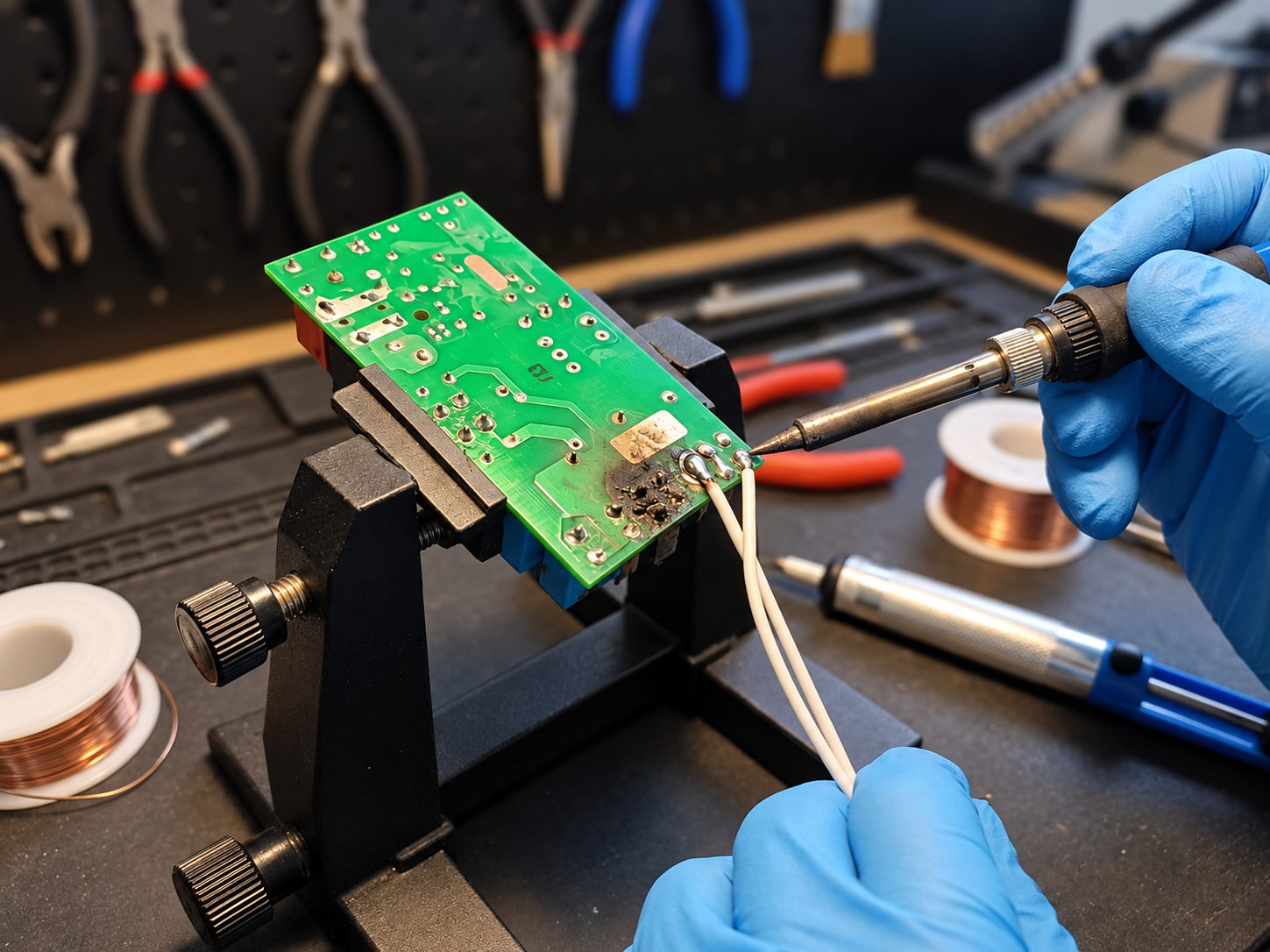
Figure 2: Repair Operation – Carbonized Substrate Cleaning and Connection Reconstruction
Using a PCB holder and a soldering iron, the technician cleans the carbonized PCB substrate around the damaged terminal area and solders new jumper wires to restore circuit integrity.
Verification and Result
Once repairs were complete, rigorous testing and verification were required to ensure the short-circuit fault was cleared and the system power logic returned to normal.
Test and Verification Steps:
-
Static Resistance Measurement: Measured the AC input terminals of the repaired input board; the resistance returned to infinity (OPEN), confirming the short circuit was eliminated.
-
Power-On Verification (Safe): Reinstalled the repaired filter board back into the machine (as shown in Figure 3, noting the new white wiring harness is connected) and replaced the main fuse. For safety, initial power-up testing was performed using an isolation transformer and a series current-limiting light bulb.
-
Final Test: The current-limiting bulb did not light up, indicating no short circuit. Mains power was then directly applied. The machine did not blow the fuse.
Result Records:
-
The green power logic LED on the main control board successfully lit up.
-
Measured the secondary low-voltage DC supply rail on the main board (such as 24VDC) using a multimeter; as shown in Figure 3, the multimeter stably displayed 24.0 V.
-
Final Result: Repair successful. The power-on fuse-blowing fault was completely resolved, system power logic returned to normal, and the machine successfully turned on.
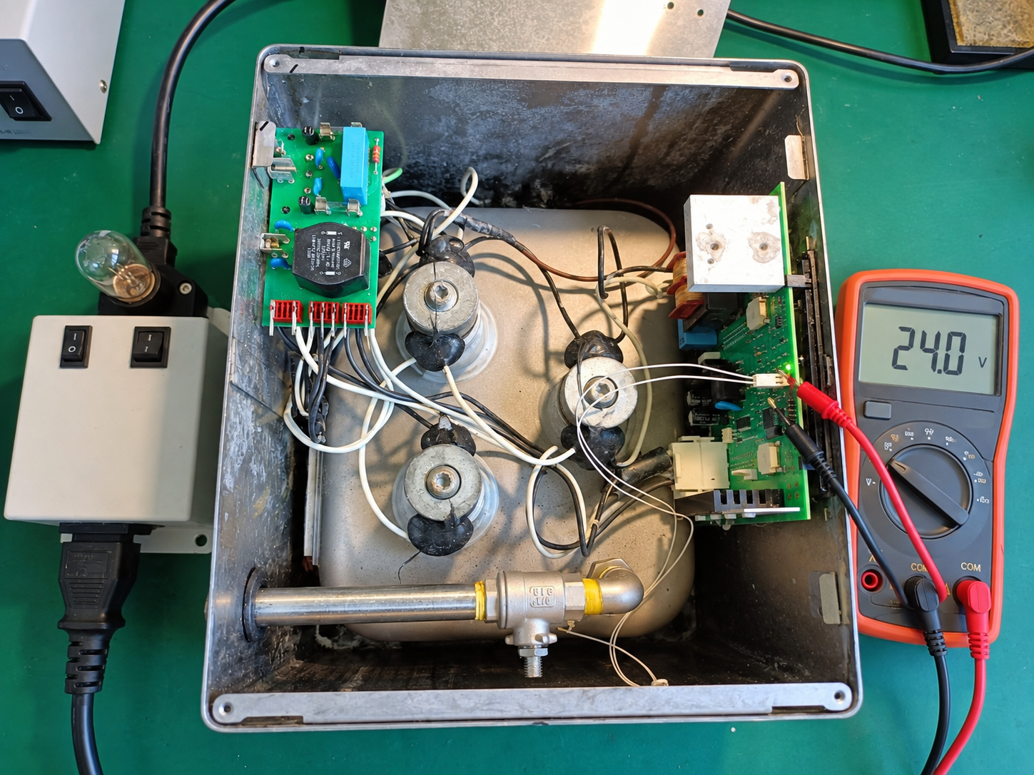
Figure 3: Final Verification – Successful Power-On and Stable Voltage
The fully reassembled ultrasonic cleaner undergoing final testing, with an isolation transformer connected on the left and a multimeter displaying a stable secondary voltage output of 24.0 V on the right.
Related Case
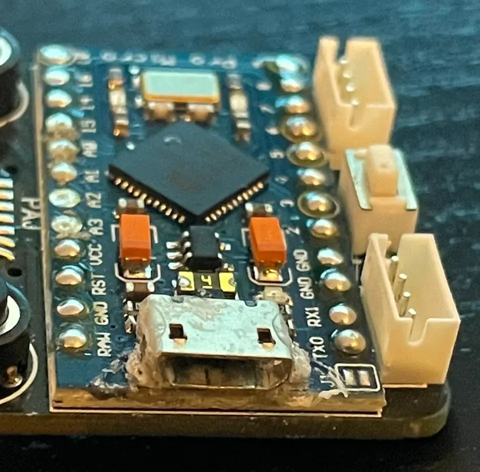
Consumer Electronics · Trace and Pad Repair
Pro Micro USB Port Repair and Trace Bridge
Fix a loose Micro USB port and broken traces on the Pro Micro board with this step-by-step micro-soldering and trace bridging guide.
View case study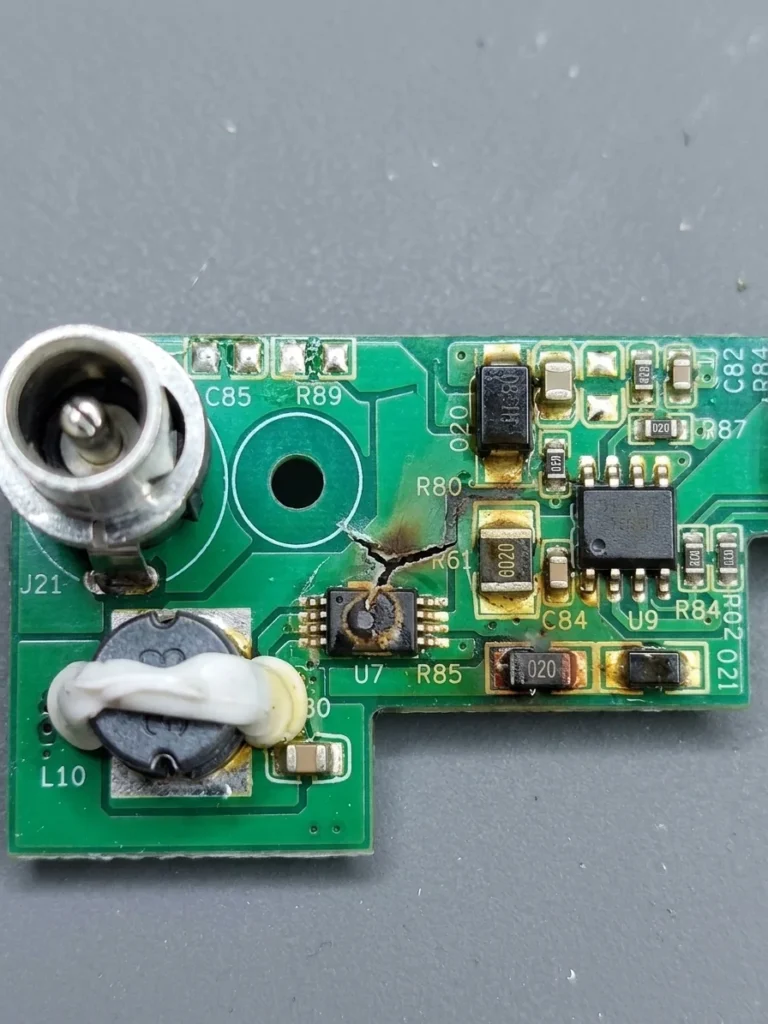
Power and Charging · Charging Board Repair
Air Mattress Pump Charging Board Repair
Assessment of a rechargeable air-mattress pump board with reported charging failure and heat damage near the DC input.
View case study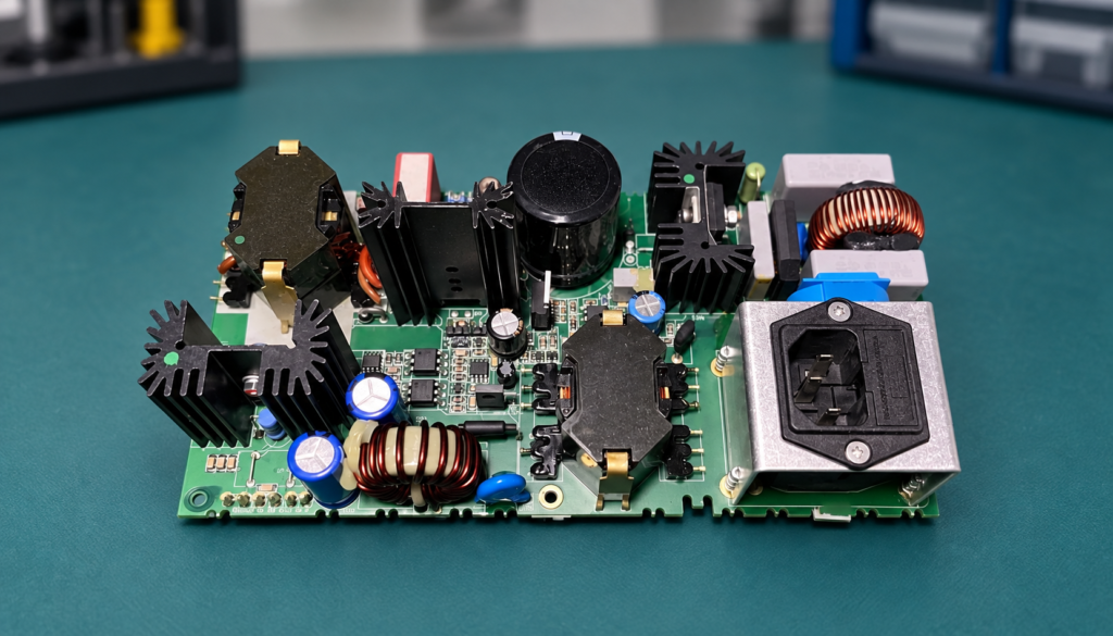
Medical Equipment · Component Replacement · Power Circuit Repair
Defibrillator AC-DC Power Module Short-Circuit Repair
The power module would not start, produced no DC output, and operated the upstream protection. Diagnosis localized the short to the secondary rectifier stage before matching-rated devices were replaced.
View case study
Industrial Control · Control Board Assessment
E11 Relay Control Board Assessment and Repair Planning
Assessment plan for a relay control board reporting E11 ‘coil not working’ even when the external coil is not connected.
View case studyDiscuss your board