
PCB Assessment Case
Mindray PM-8000 Patient Monitor Power Supply Repair
The monitor had standby power but did not respond to the power key. Diagnosis isolated a missing 12 V rail and a failed supply path to the PWM controller; documented board-level rework restored the rail and allowed the display to start.
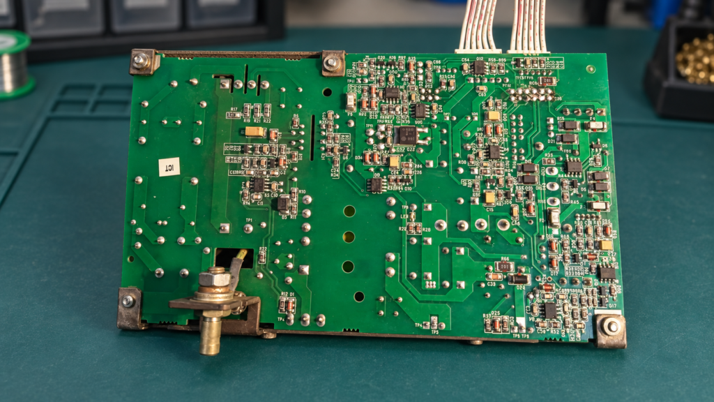
Board typePatient monitor power-supply and control board assembly
ApplicationMedical Equipment
ServicePower Circuit Repair
Case at a Glance
- Equipment: Mindray PM-8000 patient monitor.
- Reported fault: The power indicator was illuminated, but pressing the power key produced no normal startup response.
- Key finding: The 17 V input was present, while the switched 12 V rail was missing because the PWM controller VDD supply path was not active.
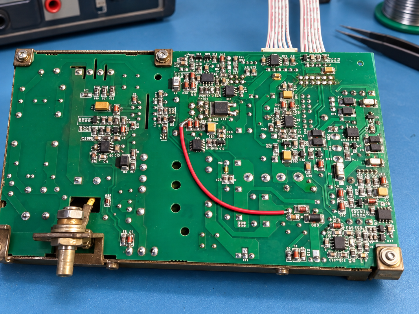
- Board-level work: The verified controller-supply path was reinstated with a documented insulated jumper specific to this board condition.
- Recorded result: The missing output returned at 12.00 V and the monitor reached its display interface during a limited bench check.
Reported Problem
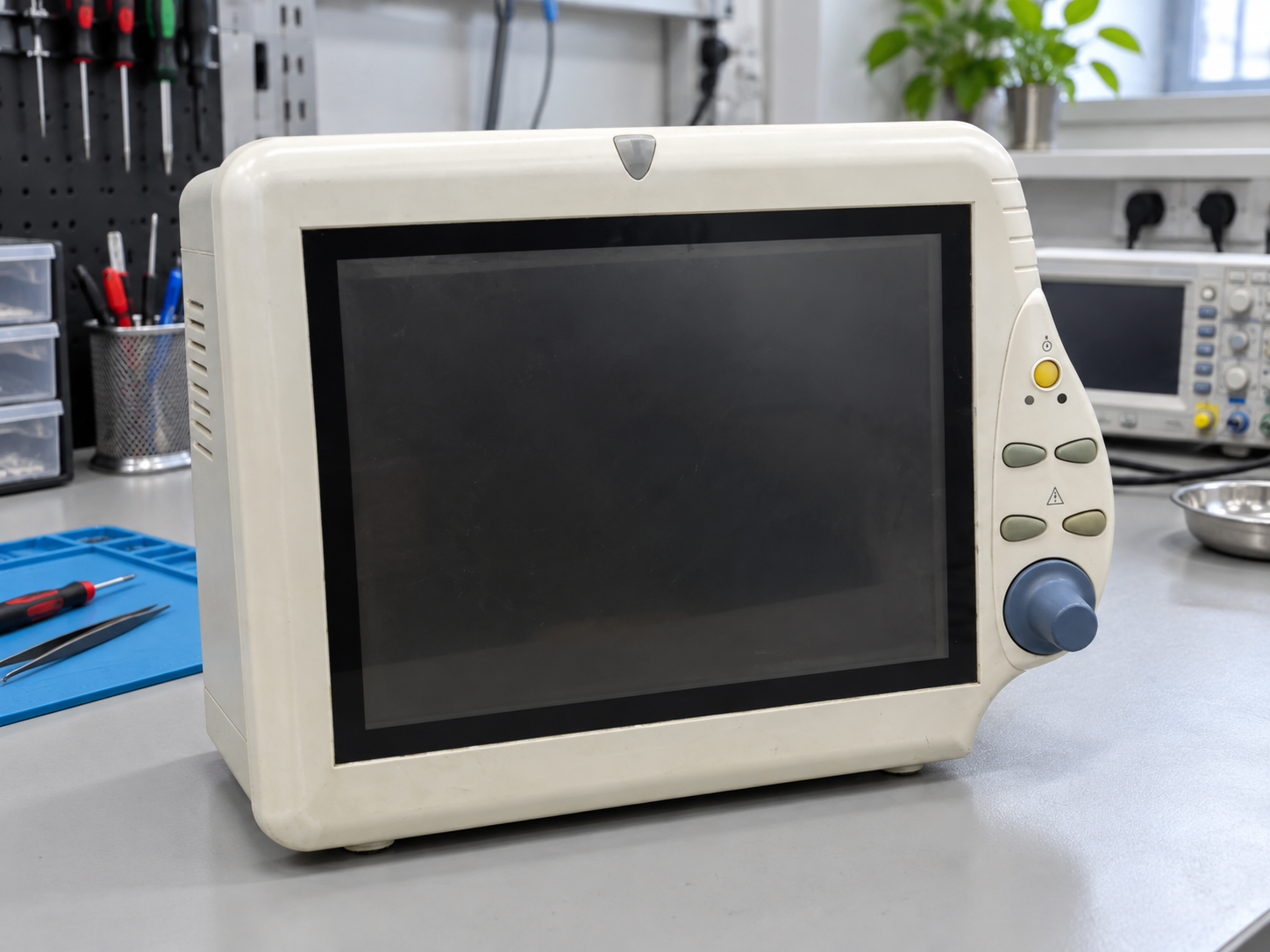
The customer reported that the Mindray PM-8000 showed a power indication but did not start when the power key was pressed. Because an illuminated indicator only confirms that part of the standby path is operating, the first objective was to determine whether the command switch, the main board, or the power-supply section was preventing startup.
Initial Checks and Fault Isolation
The power-key circuit measured approximately 5 V across the switch. Temporarily bridging the switch contacts did not change the symptom, so a simple open or intermittent power key was not supported by the test result. During internal observation, the main-board green indicator flashed briefly when the power command was given and then went out. This suggested that the unit was attempting to change state but was not sustaining the required power sequence.
A main-board substitution was then performed as a controlled comparison. The fault remained unchanged with the substitute board, which reduced the likelihood that the original main board was the primary cause and shifted the investigation toward the power-supply assembly. This step prevented unnecessary component work on a board that was not responsible for the observed symptom.
Tracing the Missing 12 V Rail
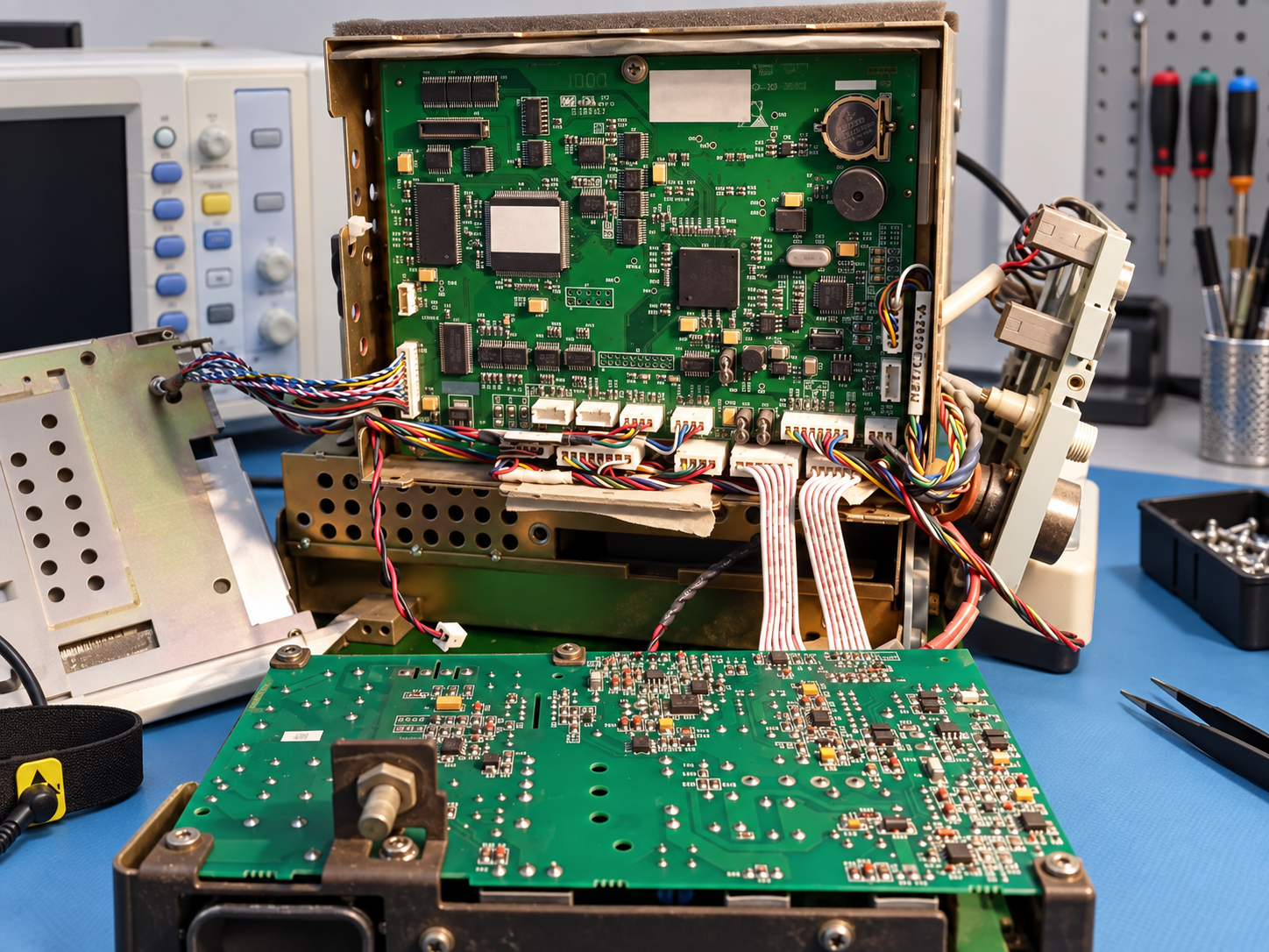
The power board accepted its 17 V DC input and the corresponding indicator remained on. Output-connector readings were then compared with a known-working power assembly during the same power-on sequence. The faulty board was missing the approximately 11.98 V output seen on the working assembly—effectively the switched 12 V rail needed by the display-side circuitry.
The supplied circuit-tracing notes showed that this 12 V rail was generated by a flyback converter from the 17 V input. The transformer primary had 17 V DC present, but the oscilloscope showed no switching waveform. The switching-device gate also had no PWM drive. Without that switching action, the transformer could not transfer energy to its secondary, which explained why the 12 V output was absent.
Diagnostic Measurements and What They Indicated
| Check | Recorded observation | Diagnostic meaning |
|---|---|---|
| Power-key circuit | Approximately 5 V across the switch | The command circuit had a control voltage available. |
| Switch bypass | Bridging the contacts produced no startup | The mechanical power key was not supported as the root cause. |
| Main-board indicator | Green LED flashed briefly, then went out | A start attempt occurred but the power sequence did not remain active. |
| Main-board substitution | The same symptom remained | The investigation moved from the main board to the power section. |
| Power-board input | 17 V DC present | The incoming supply reached the board. |
| Output comparison | The normal board had about 11.98 V; the faulty board did not | The switched 12 V rail was the missing output. |
| Transformer primary | 17 V DC but no switching waveform | The converter was not oscillating. |
| PWM drive and supply | No gate PWM; PWM controller VDD measured 0 V | The controller could not start without its supply. |
| Known-working comparison | PWM controller supply measured 17 V | The missing controlled VDD feed was confirmed as the relevant difference. |
How the Power-Control Path Was Interpreted
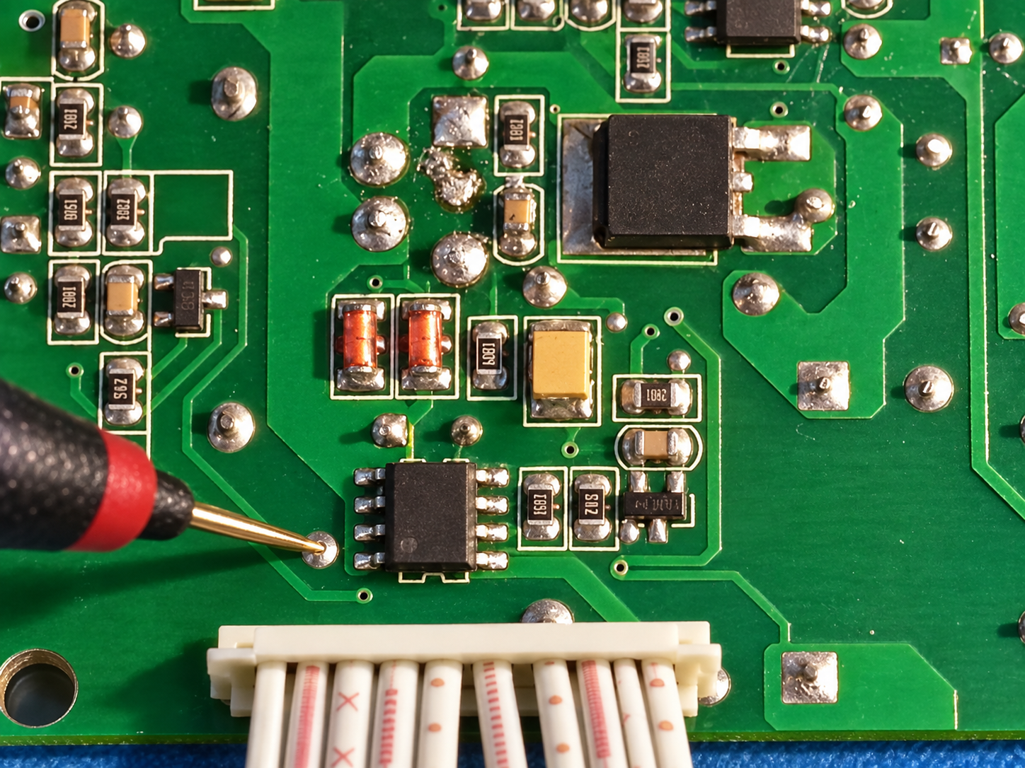
Further tracing identified the PWM function in the HC43YM-marked controller area. Its VDD pin remained at 0 V during both standby and the attempted power-on event, while the comparison board supplied approximately 17 V at the corresponding point. The repair record also mapped controlled MOSFET paths serving the 5 V-related stage and the screen supply. Those designators helped explain the board architecture; the measurements did not, by themselves, prove that Q9, Q12, or the PWM controller had internally failed.
The evidence instead supported a narrower conclusion: the controlled 17 V feed required at the PWM controller VDD path was absent. That missing feed accounted for the lack of PWM drive, the stationary transformer primary, and the missing 12 V rail. Keeping the conclusion tied to the measured path avoided replacing active devices without evidence that they were defective.
Board-Specific Repair Work
After the source and destination nodes had been verified against the working power sequence, the workshop reinstated the controller supply using an insulated jumper from the confirmed controlled 17 V source node to the PWM controller VDD point. The conductor was routed and secured to reduce movement and prevent contact with adjacent components or wiring.
This was a unit-specific board-level rework based on measurements from this power assembly. It is not a general PM-8000 modification and should not be copied to another board without reproducing the diagnosis, confirming the circuit path, checking for downstream shorts, and determining why the original feed is absent. Applying a jumper without those checks could bypass intended control or protection behavior.
Verification and Return-to-Service Limits
After the board-level rework, the previously missing output measured 12.00 V. The PM-8000 then powered on and reached its display interface during the recorded bench check. Together, the restored rail and successful startup supported the conclusion that the repaired power path addressed the reported no-start condition.
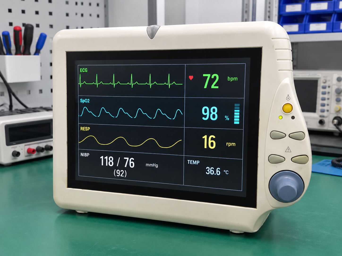
This result confirms restoration of the affected board-level power path and a limited startup/display observation only. It is not a clinical return-to-service approval. The recorded work did not certify physiological measurement accuracy, alarms, battery performance, leakage current, electrical safety, calibration, network functions, accessories, or complete operation of the patient-monitoring system. Those checks must be completed by appropriately qualified personnel under the equipment owner’s medical-device procedures before clinical use.
Need a Medical Equipment Board Evaluated?
PCB Reborn reviews medical-equipment circuit boards for evidence-bounded fault diagnosis, component-level repair, and rework. Send clear board photos, the equipment model, board identifiers, the reported symptom, and any previous measurements before shipping. See our medical equipment circuit board repair service for evaluation scope and submission guidance.
Related Case
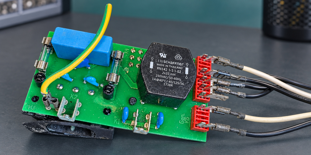
Laboratory Equipment · Medical Equipment · Power Circuit Repair · Trace and Pad Repair
Medical Ultrasonic Cleaner Input Filter Board Repair
The cleaner opened its fuse immediately at power-on. Inspection isolated a hard short on the AC input filter board, with a failed common-mode component, carbonized PCB material, and damaged connections.
View case study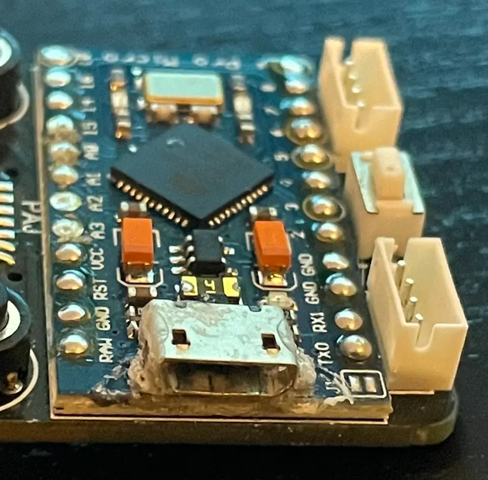
Consumer Electronics · Trace and Pad Repair
Pro Micro USB Port Repair and Trace Bridge
Fix a loose Micro USB port and broken traces on the Pro Micro board with this step-by-step micro-soldering and trace bridging guide.
View case study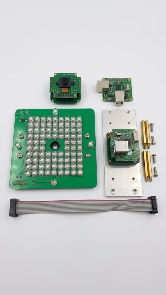
Automotive Service Equipment · Short-Circuit Diagnosis
3D Wheel Alignment Camera Board Short-Circuit Repair
Board-level assessment plan for a short-circuited 5MP camera module from an SM-V2 3D wheel-alignment system.
View case study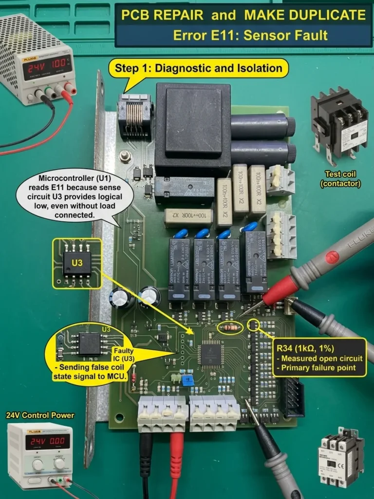
Industrial Control · Control Board Assessment
E11 Relay Control Board Assessment and Repair Planning
Assessment plan for a relay control board reporting E11 ‘coil not working’ even when the external coil is not connected.
View case studyDiscuss your board